88
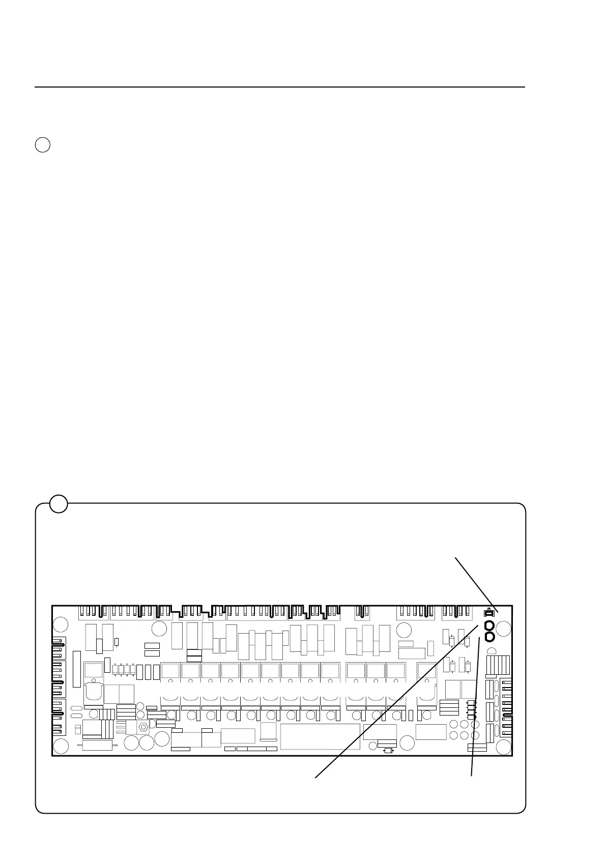
Programme unit
X4 X5 X6 X7 X8 X9 X10 X11 X12 X13 X14 X15
X1
X2
X3
X16
2 3 4 5 6 7 8 9 10 11 12 13 14
Red LED:
Steadyredlight=voltage
supply OK.
Green LED:
Quickblinks=communicationbetweentheI/O
card and CPU card is OK.
Pushbutton SW1: Used as an acknowledgement button for programming of
the order of the I/O cards (see the section “Replacing the I/O card”).
1
3973
5
5
I/O cards
The I/O cards are controlled by the CPU card and communicate via
a serial interface. Depending on the need for inputs and outputs, one
programme unit may have one or two I/O cards.
All inputs and outputs are switched from the I/O card to the various
functions via the communication cards in the rear electric module.
Each I/O card is connected to a separate communication card: I/O
card A11 uses communication card A21 and I/O card A12 uses com-
munication card A22.
There are inputs for door lock and external switches (e.g. Start/Stop
and Pause). Signals on these inputs are passed on to the CPU card.
The outputs control water valves, detergent supply, drain and hea-
ting.
The voltage supply to the CPU and I/O cards takes place via I/O card
1 A11, which feeds voltage to both the CPU card A1 and a possible
I/O card 2 A12.
Note that if the programme unit uses two cards and one needs to be
replaced, special programming is required. It is necessary to pro-
gramme the new card with the correct I/O card number (1 or 2) using
a laptop and special software. See the section “Replacing the I/O
card”.