1726 North Ballard Road, Suite 1 - Appleton, WI 54911 - 920.991.9082
Technical Support 855.804.5774 - Parts@waupacaelevator.com
PTM30136-F
22 MAR 2018
W
E
CRUSH
HAZARD
CUTTING
HAZ ARD
CRUSH
HAZARD
CRUSH
HAZARD
CRUSH
HAZARD
CRUSH
HAZ ARD
FALLING
HAZ ARD
CRUSH
HAZARD
KINK
HAZ ARD
CRUSH
HAZARD
PINCH
HAZ ARD
3"
1-1/2"
DEAD SIDE
(NON LOAD
BEARING)
WEDGE
LIVE SIDE
(LOAD BEARING)
CABLE
CLAMP
ASSEMBLED
A
B
RETAINER PIN
SHACKLES
RAM HEADER
4.
2.
1.
1
6.
3.
A)
5.
B)
2
6
7.
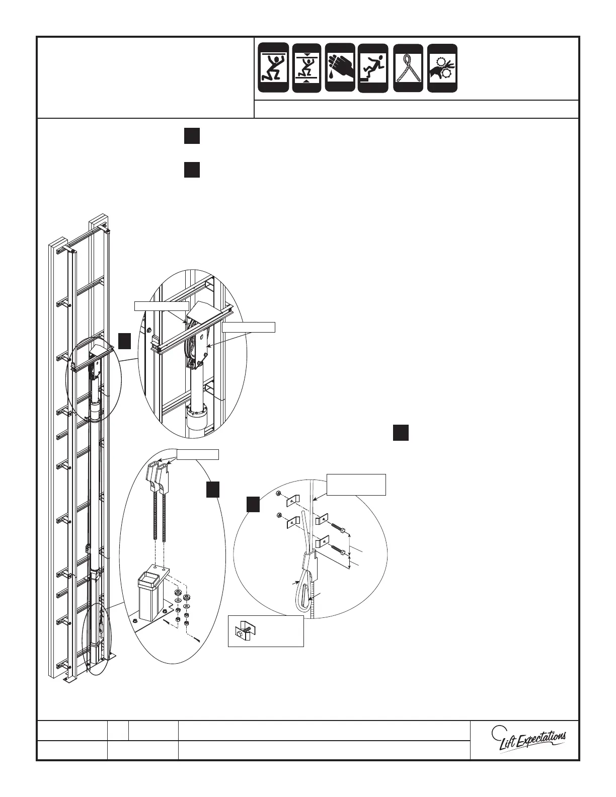
SERIES : 116
WIRE ROPE &
SHACKLE INSTALLATION
Remove hardware and place shackle rods in pedestal base. Then reinstall
previously removed hardware so shackle has max adjustment remaining.
Route the wire ropes over the ram header sheave. Verifying the wire ropes are
fully seated in each groove and under the retainer pins. Verify even weight
distribution of the wire ropes on each side ram header sheave.
Secure the wire ropes from any unintended
movement as they may cause damage to the
hoistway/components or cause injury to the
installers.
Note: Verify wire ropes are not crossed
at any point throughout their complete
length.
Route the wire rope closet to the rail wall
through the shackle socket closest to the rail
wall in the pedestal base. Create a loop by
routing wire rope back through the shackle
socket. Insert wedge into the newly created
loop.
Pull the wire rope and wedge
tightly into the socket. Repeat this
for other shackle.
Fasten (4) cable clamps into the
designated locations as described
below:
The rst clamp shall be
placed a maximum of 4 times
the rope diameter above the
shackle.
(example: 3/8” wire rope=
maximum distance of
1-1/2”).
The second clamp shall be
located within 8 times the
rope diameter above the rst
clamp.
(example: 3/8” wire rope =
maximum distance of 3”).
Note: Verify the live side
cable and dead side tail are
as close as possible once the
clamp is secure. Then secure
the tail.
Securely attach the wire rope tag.
 Loading...