1726 North Ballard Road, Suite 1 - Appleton, WI 54911 - 920.991.9082
Technical Support 855.804.5774 - Parts@waupacaelevator.com
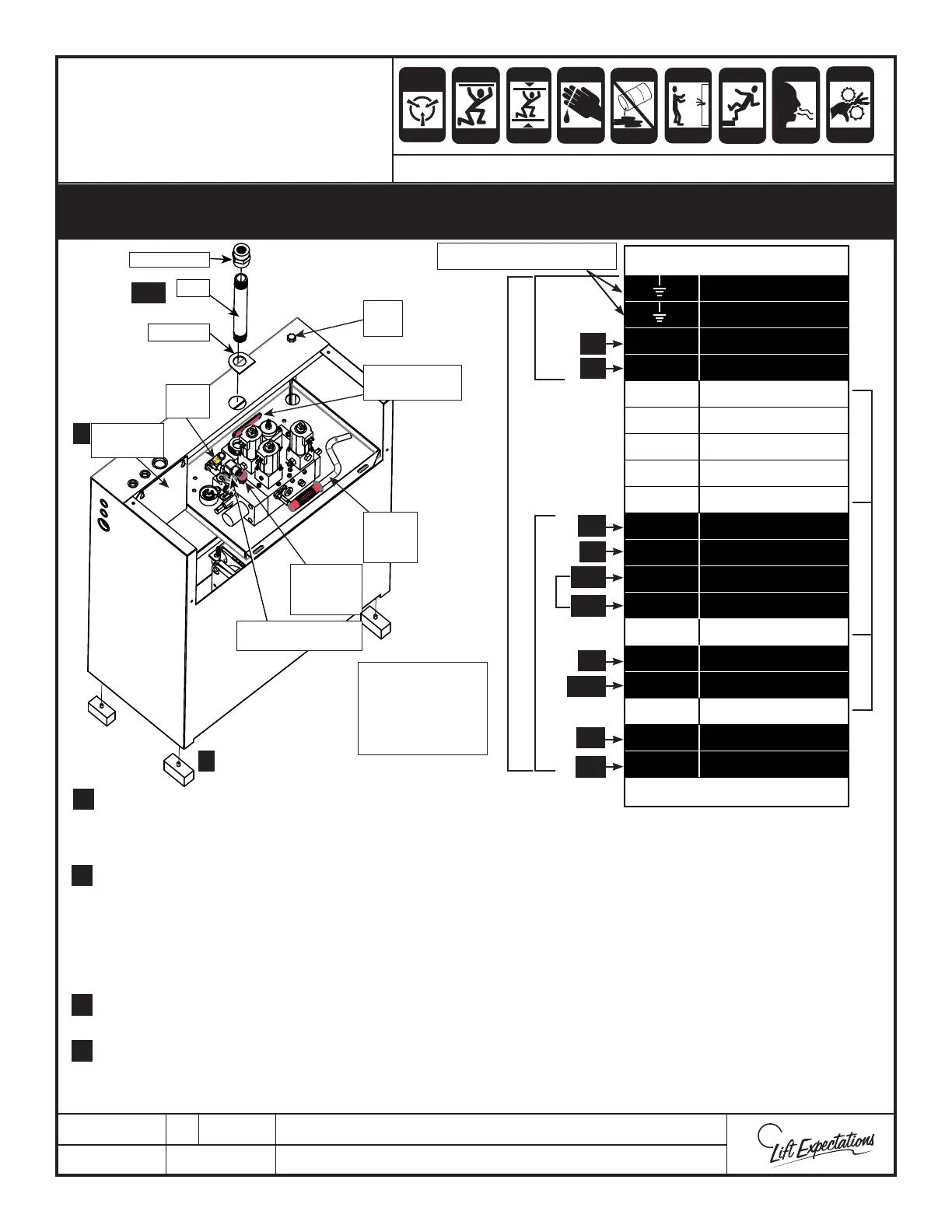
PTM30065-H
7 MARCH 2018
Valve Terminals
Ground
Ground
T1 Motor
T2 Motor
T3 Motor
14 SM110 Power
13 SM110 Power
12 Thermal Cut - Out
11 Thermal Cut - Out
10 COM
9 VMP/S
8 LPS
7 LPS
6
5 VML-
4 VML+
3
2 VMD-
1 VMD+
Controller Connection
CRUSH
HAZARD
CUTTING
HAZ ARD
CRUSH
HAZARD
CRUSH
HAZARD
CRUSH
HAZARD
CRUSH
HAZ ARD
ELECTRIC
HAZ ARD
FALLING
HAZ ARD
CRUSH
HAZARD
PINCH
HAZ ARD
ANTI-
STATIC
ALERT
ECO-SYSTEM
HAZ ARD
INHALATION
HAZ ARD
Do not allow the hydraulic oil to become contaminated with foreign debris by maintaining
a clean work environment. Always keep the tank cover sealed and secured and do not lift the tank
when its lled with hydraulic uid.
1. Insert the (4) rubber feet into bottom of power unit.
2. Remove temporary plugs, by unscrewing the plug located in the ball valve in the back of the tank. Also
remove the plug on top of the tank were the pipe goes through.
3. Securely install the gasket, pipe and pipe tting into the valve assembly.
4. Route the hydraulic hose if supplied, between the piping from the jack to pipe connection on the top of the
power unit. Fill in the blanks on the exible hose tag. (route hose per ASME A17.1/CSA B44 and local code)
Note: The hydraulic hose will shrink when pressurized. Be sure there’s slack between the piping and the
hydraulic power unit to accommodate this.
5. Attach the hydraulic hose to the pump tting with hydraulic thread compound on threads.
(attach hose per ASME A17.1/CSA B44 and local code)
6. Wire power unit to the controller using electrical schematic.
(hydraulic power unit and wiring must meet N.E.C. and local code)
7.
Note: The terminal mounting plate can be removed for ease of wiring.
Note:
Do not jumper
terminals 2-5 at the
hydraulic tank
terminals
HAND
PUMP
HANDLE
DIP
STICK
OIL SHUT OFF
VALVE HANDLE
PUMP
TERMINALS
HAND
PUMP
MANUAL
LOWERING
BUTTON
PIPE FITTING
PIPE
GASKET
LPS
(LOW PRESSURE SWITCH)
W
E
10 GA14 GA
WEC USES THE BLACK CONTROL TERMINALS
T1
VC
T2
LPS
SV
LPS
HSV
DV
VC
VC
To Controller Ground Lug
WHITE PUMP TERMINALS WEC DOES NOT USE
18 GA
SERIES : 114 , 116
GMV/OLS
HYDRAULIC POWER UNIT
INSTALLATION
3, 5
6.
6
3.
5.
1.
1
 Loading...