1726 North Ballard Road, Suite 1 - Appleton, WI 54911 - 920.991.9082
Technical Support 855.804.5774 - Parts@waupacaelevator.com
PTM30133-G
22 MAR 2018
W
E
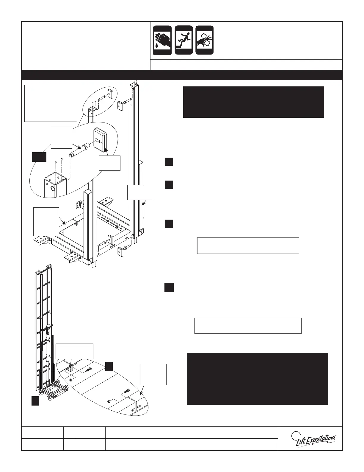
GUIDE
BLOCK
PIN
GUIDE
BLOCK
INSTALLATION
CLAMP
SLING
UPRIGHT
SLING
UPRIGHT
CROSS
ANGLES
UPRIGHT
CROSS
ANGLES
CRUSH
HAZARD
CUTTING
HAZ ARD
FALLING
HAZ ARD
CRUSH
HAZARD
PINCH
HAZ ARD
CAR STABILIZER
BRACKETS NOT
SHOWN
FOR CLARITY
UNIT DEPICTED WITH ALL SLING EXTENSION
OPTIONS SHOWN. EXTENSION LAYOUT MAY
CHANGE DEPENDING ON APPLICATION.
NOTE:
THERE MUST BE A SLIGHT GAP BETWEEN BOTH
UPRIGHT CROSS ANGLES. IF THE INSTALLATION
CLAMPS ARE FASTENED TIGHT AGAINST EACH
OTHER THE SLING WILL NOT SLIDE FREELY IN THE
RAIL SYSTEM.
Verify all sling extensions are on or inserted in the sling before bringing sling into the hoistway.
1.
2.
3.
4.
6.
5.
2, 3
6
4
Note: The top of the sling base should
be 2 “below the lowest oor landing.
Note: Verify sling uprights are true to
the rail. Ratchet strap may assist in this.
SERIES : 115, 116, 118
Insert guide block pins into the (4) pin sleeves located on the
inside of the sling. Verify pins anges are tight to sling tube.
(Locate the two (2) adjustable pins at the top of the sling).
Using the provided (8) - 1/4”-28 set screws securely fasten the
guide block pins in position.
Press (4) guide blocks in position on the guide block pins.
Verify the guide block holes are all o set in the correct
orientation as shown with the thick part towards the rail
backing once installed.
Bring the sling halves into the hoistway and block up as
required.
Set the right and left sides of the sling in position in the rail.
Fasten the right and left halves together with the installation
clamps using the following provided hardware:
(2) - 3/8”-16 x 1-1/4” Hex Bolts
(2) - 3/8” Nylock Nuts
SLING ASSEMBLY AND
SAFETY INSTALLATION