1726 North Ballard Road - Appleton, WI 54911 - 920.991.9082
Technical Support 800.238.8739 - TechSupport@WaupacaElevator.com
PTM30118-C
12/11/2012
W
E
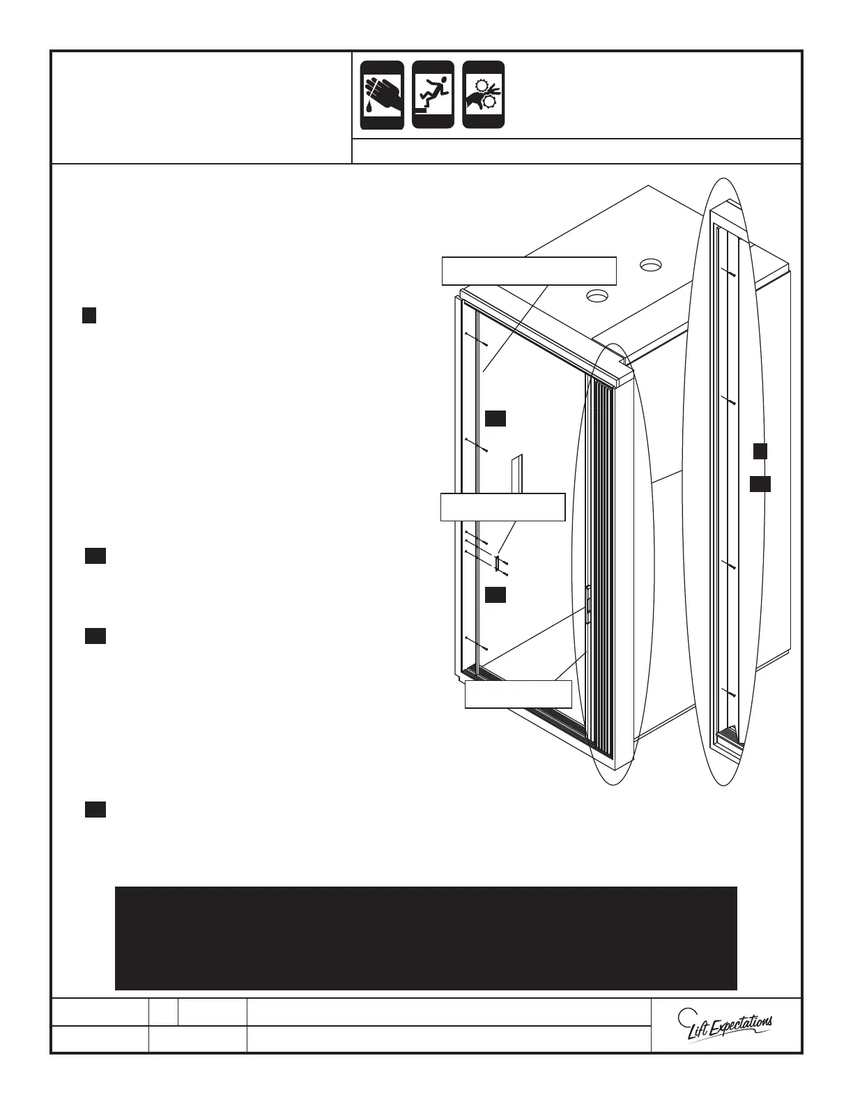
GATE STRIKE JAMB
STRIKE PLATE
LEAD POST
CRUSH
HAZARD
CUTTING
HAZARD
FALLING
HAZARD
CRUSH
HAZARD
PINCH
HAZARD
ACCORDIAN GATE
INSTALLATION
SERIES : 008 -114- 115- 116 - 118 - 021 - 022 - 210
7 Stand inside the car, and push the gate to the stack
side. Let the gate form its own plumb, and carefully
mark a line with a nonpermanent mark on the
wall/pocket/post at the edge of the mounting panel
near the top and bottom. It is important to make this
mark while the gate is in the stacked position.
8 Extend the gate to have access to the mounting panel.
Hold the mounting panel edge at the nonpermanent
marks. Note, the position of the mounting panel
may move away from the marks as the gate is
extended open. The panel position must be
maintained at the marked edge. Fasten mounting
panel in place with (2) - #6 x 1-1/2” at head screws
8” down from the ceiling and 8” up from the oor.
9 Stack the gate against the mounting panel to form a
neat, tight stack. Do not force the stack into position.
If gate stack binds, the mounting panel moved from
the marked edge, and the previous step needs to be
repeated.
10 Once the gate stacks properly, re-extend the gate and
fasten the mounting panel with (2) - #6 x 1-1/2” at
head screws between the rst (2) screws evenly
splitting the distance.
11 Dry t the gate strike jamb against the opposite wall
of the stack. The strike jamb needs to be centered
with the top gate track and the oor track groove.
Slide the gate lead post over to the strike to verify
proper placement. Fasten the gate strike jamb with
(4) - #6 x 1-1/2” at head screws.
12 Center the strike plate on the magnet with the
adhesive side out. Remove the protective tape from
the adhesive backing, and push the door rmly shut.
13 Slide the gate open while pressing on the strike plate
with a small athead screw driver to maintain placement. Drill through the center of each strike plate screw hole and
gate strike jamb using a 3/32” drill bit. Fasten the strike plate in place with (2) - #6 x 1-1/2” at head screws.
14 If provided, install gate operator at this time (reference gate operator installation manual).
VERIFY ALL FASTENERS ARE SECURELY FASTENED. VERIFY THE GATE OPENS AND
CLOSES WITH SMOOTH OPERATION. THE GATE MUST STACK TIGHT IN THE OPEN
POSITION AND LATCH ON THE MAGNET WITH NO VISABLE GAPS BETWEEN THE
GATE STRIKE AND LEAD POST.
8
10
11
13
8
10
11
13
 Loading...