When the concentrator receives a response from the device, it will impose a delay equivalent
to the “InterFrame” parameter between the last byte of the last received frame and the first
byte of the next frame it sends to that device. The time is valid for the entire bus. So, if a new
frame is emitted to another device than the previous one, the delay will nevertheless be
applied.
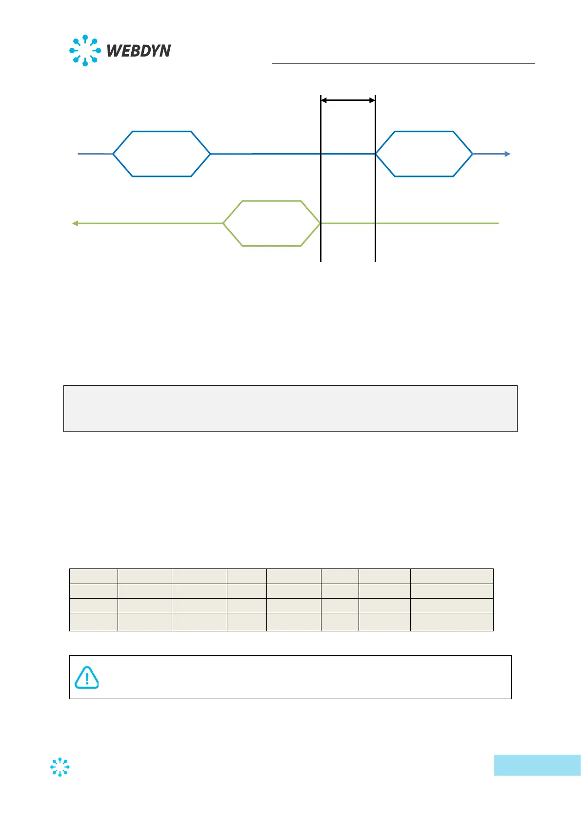
Below is a serial interface configuration example:
type;baudrate;data_bits;parity;stop_bits;wires;protocol;interframe(ms)
SERIAL1;9600;8;N;1;2;Modbus;0
SERIAL2;1200;8;N;1;4;SMANET;0
SERIAL3;19200;8;N;1;2;PW1;0
In this example, the first serial port is configured at 9600 bauds, 8 data bits, no, parity, 1 stop
bit, 2 communication wires, “modbus” protocol and no inter-frame time.
The 2
nd
serial port is configured at 1200 bauds, 4 wires to be used with the SMA-Net protocol.
The 3
rd
serial port is configured at 19200 bauds, 2 wires to be used with the PowerOne
protocol.
When editing this file using Excel, the following display is shown using the CSV format:
If the file is modified using “Excel” type spreadsheet software, the format may be
modified and the “;” delimiters replaced by “,”, making it unusable by the
concentrator. Always make sure to indicate the delimiter format when saving.
 Loading...