54 2576780000/00/02-2018
Technical Data
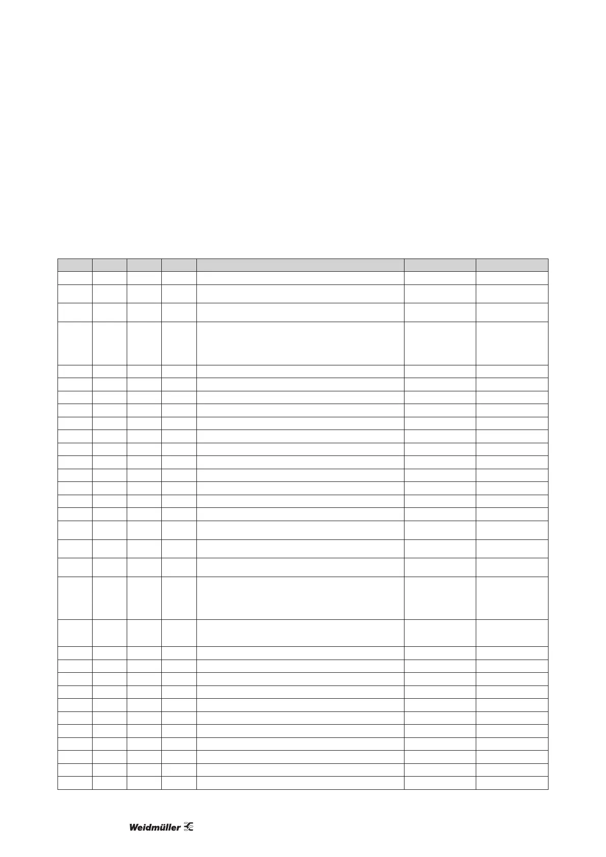
Parameter and Modbus address list
The following excerpt from the parameter list contains settings that are necessary for proper operation of the Energy Meter 610/610-PB,
such as current transformers and device addresses. The values in the parameter list can be written and read.
In the excerpt, the measured value list les the measured and calculated measured values, output status data and recorded values so
that they can be read.
Table 1 - Parameter list
Address Format RD/WR Unit Note Adjustment Range Default
0 SHORT RD/WR - Device address (Modbus/Probus) 0 to 255
1)
1
1 SHORT RD/WR kbps Baud rate for Modbus (0 = 9.6 kbps, 1 = 19.2 kbps, 2 = 38.4 kbps,
3 = 57.6 kbps, 4 = 115.2 kbps)
0 to 7 (5 to 7 only for
internal use)
4
2 SHORT RD/WR - Modbus Master
0 = Slave
0, 1 0
3 SHORT RD/WR - Stopbits
0 = 1 Bit, none parity
1 = 2 Bits, none parity
2 = 1 Bit, even parity
3 = 1 Bit, uneven parity
0 to 3 0
10 FLOAT RD/WR A Current transformer I1, primary 0 to 1000000
2)
5
12 FLOAT RD/WR A Current transformer I1, secondary 1 to 5 5
14 FLOAT RD/WR V Voltage transformer V1, primary 0 to 1000000
2)
400
16 FLOAT RD/WR V Voltage transformer V1, secondary 100, 400 400
18 FLOAT RD/WR A Current transformer I2, primary 0 to 1000000
2)
5
20 FLOAT RD/WR A Current transformer I2, secondary 1 to 5 5
22 FLOAT RD/WR V Voltage transformer V2, primary 0 to 1000000 400
24 FLOAT RD/WR V Voltage transformer V2, secondary 100, 400 400
26 FLOAT RD/WR A Current transformer I3, primary 0 to 1000000 5
28 FLOAT RD/WR A Current transformer I3, secondary 1 to 5 5
30 FLOAT RD/WR V Voltage transformer V3, primary 0 to 1000000 400
32 FLOAT RD/WR V Voltage transformer V3, secondary 100, 400 400
34 SHORT RD/WR Hz Frequency determination
0 = Auto, 45 to 65 = Hz
0, 45 to 65 0
35 SHORT RD/WR - Display contrast
0 (low), 9 (high)
0 to 9 5
36 SHORT RD/WR - Backlight
0 (dark), 9 (light)
0 to 9 6
37 SHORT RD/WR - Display prole
0 = default display prole
1 = default display prole
2 = vdefault display prole
3 = freely selectable display prole
0 to 3 0
38 SHORT RD/WR - Display change prole
0 to 2 = default display change proles
3 = freely selectable display change prole
0 to 3 0
39 SHORT RD/WR s Changeover time 0 to 60 0
40 SHORT RD/WR - Averaging time, I 0 to 8 * 6
41 SHORT RD/WR - Averaging time, P 0 to 8 * 6
42 SHORT RD/WR - Averaging time, U 0 to 8 * 6
45 USHORT RD/WR mA Response threshold of current measuring I1 to I3 0 to 200 5
50 SHORT RD/WR - Password 0 to 999 0 (Kein Passwort)
100 SHORT RD/WR - Address of the measured value, Digital output 1 0 to 32000 874
101 SHORT RD/WR - Address of the measured value, Digital output 2 0 to 32000 882
102 FLOAT RD/WR Wh Pulse value, Digital output 1 -1000000 to +1000000 1000
104 FLOAT RD/WR Wh Pulse value, Digital output 2 -1000000 to +1000000 1000
106 SHORT RD/WR 10ms Minimum pulse length (1 = 10 ms) Digital output 1/2 1 to 1000 5 (= 50 ms)