552576780000/00/02-2018
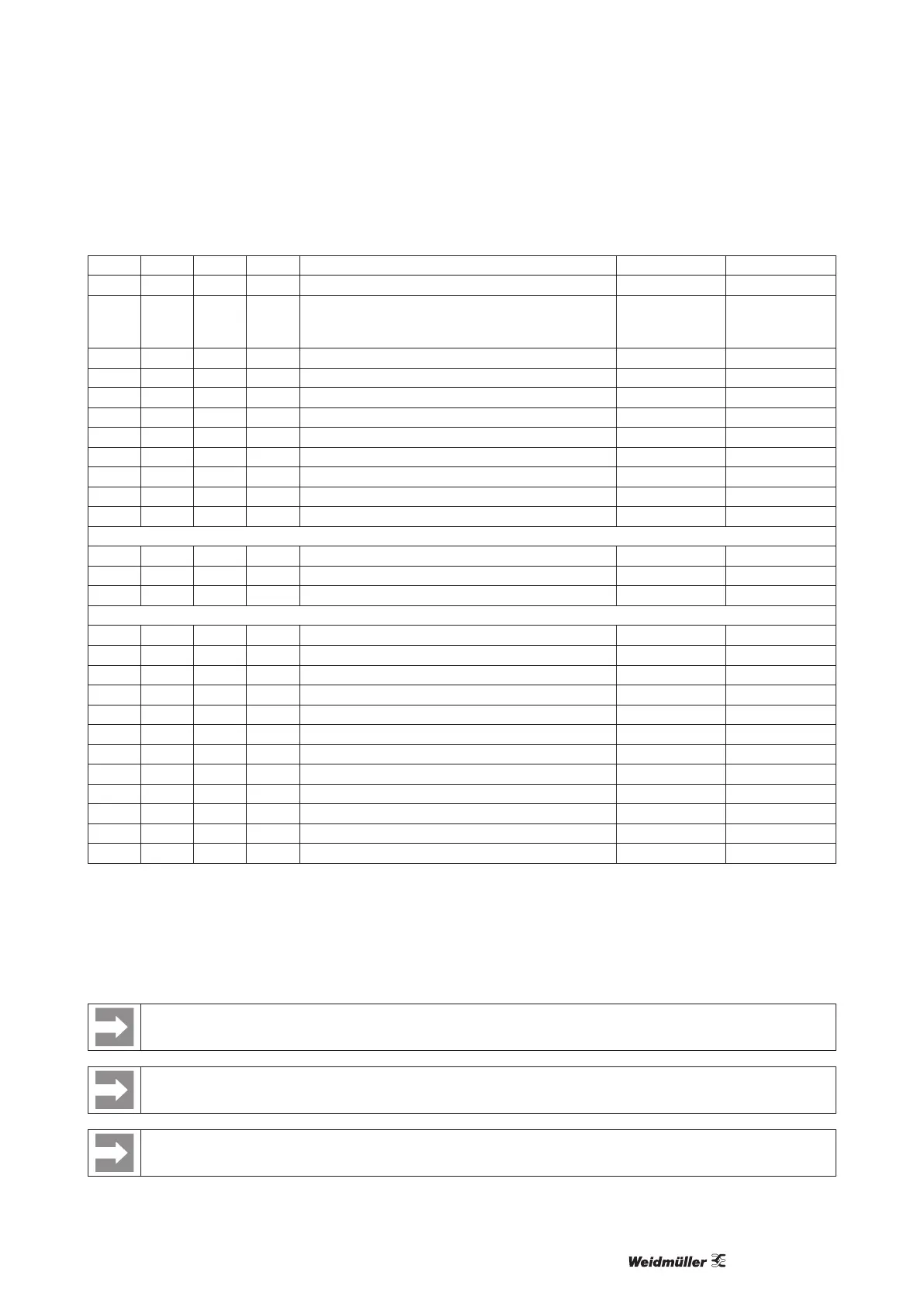
Technical Data
206 SHORT RD/WR s “Drag indicator” period duration 300 to 3600 900
207 SHORT RD/WR s “Drag indicator” capture time 1 to 20 10
208 SHORT RD/WR - Cong. Digital input 1
0 = internal synchronisation
1 = external synchronisation (NO)
2 = external synchronisation (NC)
0 to 2 0
500 SHORT RD/WR - Terminal assignment, I L1 -3...0...+3
1)
+1
501 SHORT RD/WR - Terminal assignment, I L2 -3...0...+3
1)
+2
502 SHORT RD/WR - Terminal assignment, I L3 -3...0...+3
1)
+3
503 SHORT RD/WR - Terminal assignment, U L1 0 to 3
1)
1
504 SHORT RD/WR - Terminal assignment, U L2 0 to 3
1)
2
505 SHORT RD/WR - Terminal assignment, U L3 0 to 3
1)
3
506 SHORT RD/WR - Clear min. and max. values 0 to 1 0
507 SHORT RD/WR - Clear energy meter 0 to 1 0
508 SHORT RD/WR - Force write EEPROM 0 to 1 0
Note: Energy values and minimum and maximum values are written to the EEPROM every 5 minutes.
509 SHORT RD/WR - Voltage connection diagram 0 to 8
2)
0
510 SHORT RD/WR - Current connection diagram 0 to 8 0
511 SHORT RD/WR - Relative voltage for THD and FFT 0, 1 0
The voltages for THD and FFT can be shown on the display as L-N or L-L values. 0 = LN, 1 = LL
512 SHORT RD/WR - Year 0 to 99
513 SHORT RD/WR - Month 0 to 12
514 SHORT RD/WR - Day 0 to 31
515 SHORT RD/WR - Hour 0 to 24
516 SHORT RD/WR - Minute 0 to 59
517 SHORT RD/WR - Second 0 to 59
600 UINT RD/WR - Metering range exceedance 0 to 0xFFFFFFFF
746 SHORT RD/WR s Period of time after which the backlight will switch to standby 60 to 9999 900
747 SHORT RD/WR s Brightness of the standby backlight 0 to 9 0
750 SHORT RD - Software release
754 SERNR RD - Serial number
756 SERNR RD - Production number
(*1) Values 0 and 248 through 255 are reserved and may not be used.
(*2) The adjustable value of 0 does not produce any useful work values and must not be used.
* 0 = 5 seconds; 1 = 10 seconds.; 2 = 15 seconds; 3 = 30 seconds; 4 = 1 minute; 5 = 5 minutes; 6 = 8 minutes; 7 = 10 minutes;
8 = 15 minutes
1) 0 = No measurement of the current or voltage path.
2) The setting 8 is equal setting 0.
A complete overview of the parameters and measured values as well as explanations regarding the selected measured values
is led in the document “Modbus Address List” in the Internet on the product pages.
The addresses contained in the description can be adjusted directly on the device in the range from 0 to 800. The address
range above 1000 can only be processed via modbus!
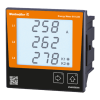
Only the rst three positions (###) of a value are shown on the display. Values larger than 1,000 are marked with “k”. Example:
003k = 3000