Operation
1203−1/A1
Winterthur Gas & Diesel Ltd.
3/ 3
2. Lubrication
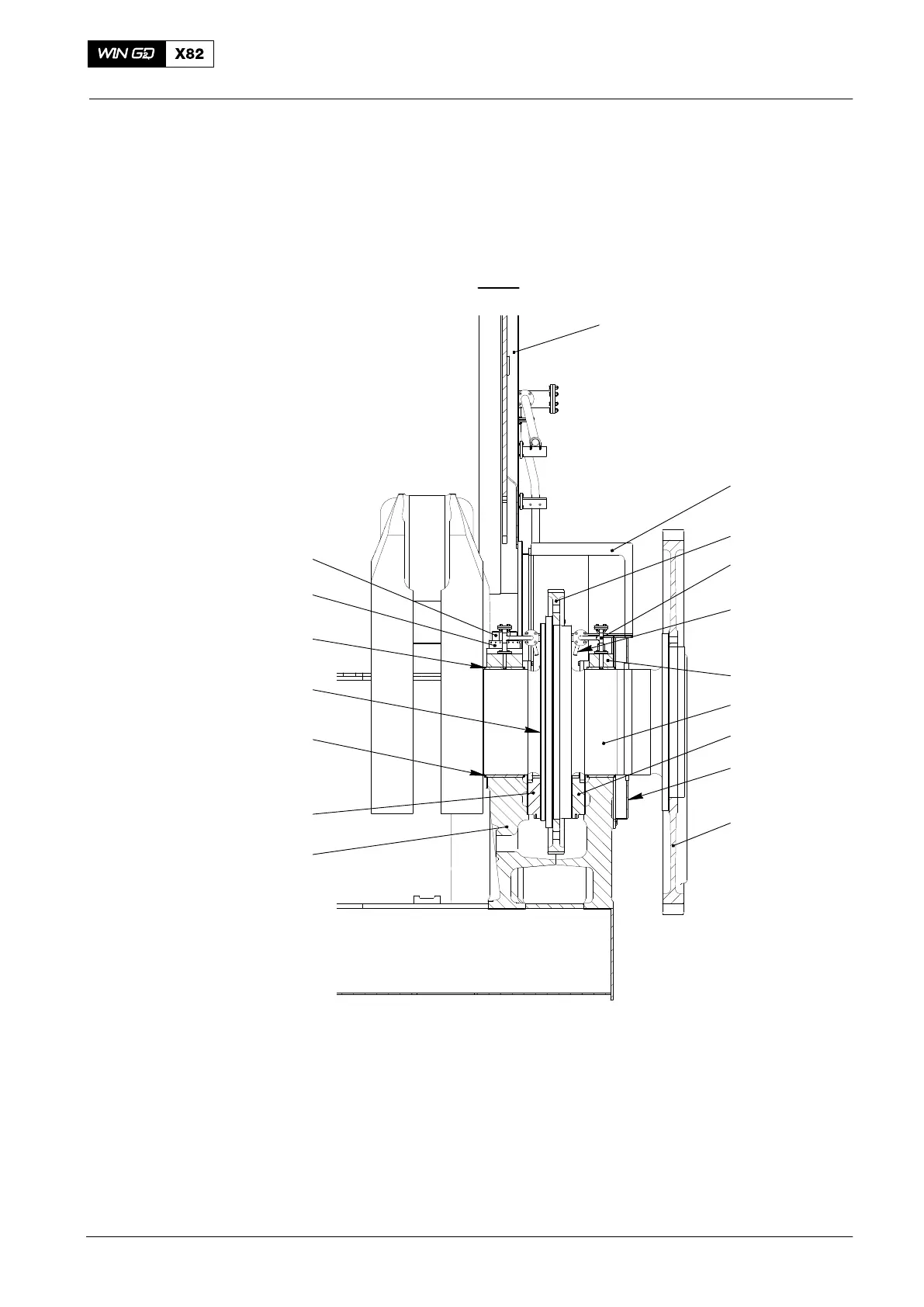
During operation, bearing oil flows through the oil pipe (2, Fig. 2) to the two
nozzles (3). The oil flows out of the two nozzles (3) as a spray, which becomes an oil
layer between the thrust bearing flange (17) and the thrust pads (5, 13).
20
19
18
16
5
4
10
11
2
3
7
12
13
14
15
1
17
018.088/09
I - I
Fig. 2: Longitudinal Section
1 Column 13 Thrust pad (driving end)
2 Oil pipe 14 2-part oil baffle
3 Nozzle 15 Flywheel
4 Bedplate 16 Lower bearing shell
5 Thrust pad (free end) 17 Thrust bearing flange
7 Bearing cover 18 Upper bearing shell
10 End casing 19 Round nut
11 Crankshaft gear wheel 20 Waisted stud for bearing cover
12 Crankshaft
Thrust Bearing
2017−08