Operation5556−2/A1
Winterthur Gas & Diesel Ltd.
4/ 5
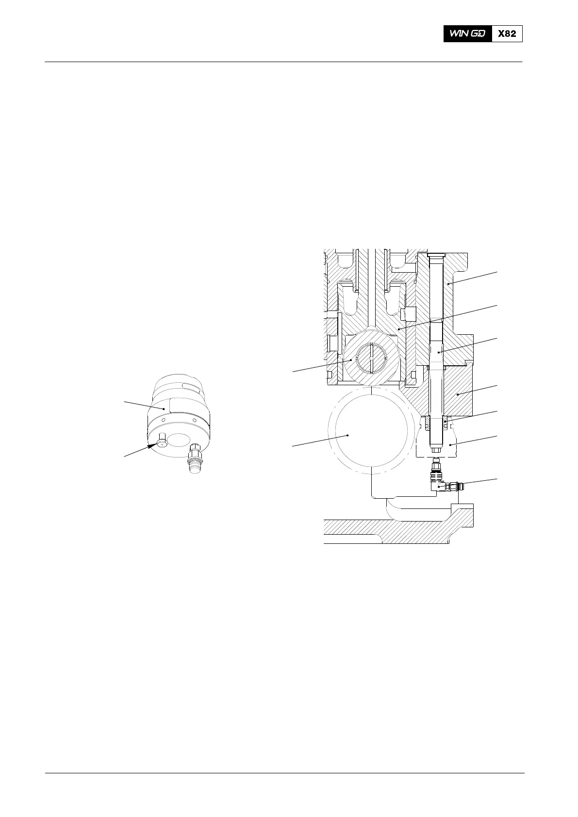
11) Put the pre-tensioner (6, Fig. 3) on to the elastic bolt (3). The pre-tensioner must
touch the pad (4).
12) Use the pre−tensioner (6) for tensioning the elastic bolt (3) (see the procedure in
the Maintenance Manual 9403−4).
13) Remove the pre-tensioner (6) (see the procedure in the Maintenance Manual
9403−4).
14) Make sure that the roller (10) stays approximately 3.0 mm above the cam (9).
15) Install the inspection cover (6, Fig. 2).
Note: For the torque values and lubrication of the applicable screws, see the
Maintenance Manual 0352−1.
6
8
016.909/08
1
2
3
4
5
6
7
7
10
Fig. 3: Assembly of Roller Lifter Tool 94430
1 Casing (fuel pump unit) 6 Pre−tensioner (tool 94430a)
2 Guide piston 7 Coupling element (tool 94934g)
3 Elastic bolt (part of tool 94430) 8 Vent screw
4 Pad (part of tool 94430) 9 Cam
5 Round nut (part of tool 94430) 10 Roller
2017−08
Fuel Pump − Cutting Out and Cutting In