Operation6500−1/A1
Winterthur Gas & Diesel Ltd.
2/ 2
9109
6
5
4
3
2
1
78
12
18
EO FA
EG
PU
RS AS
11
WD
WS
16
17
15
1413
9
OW
SA
016.747/08
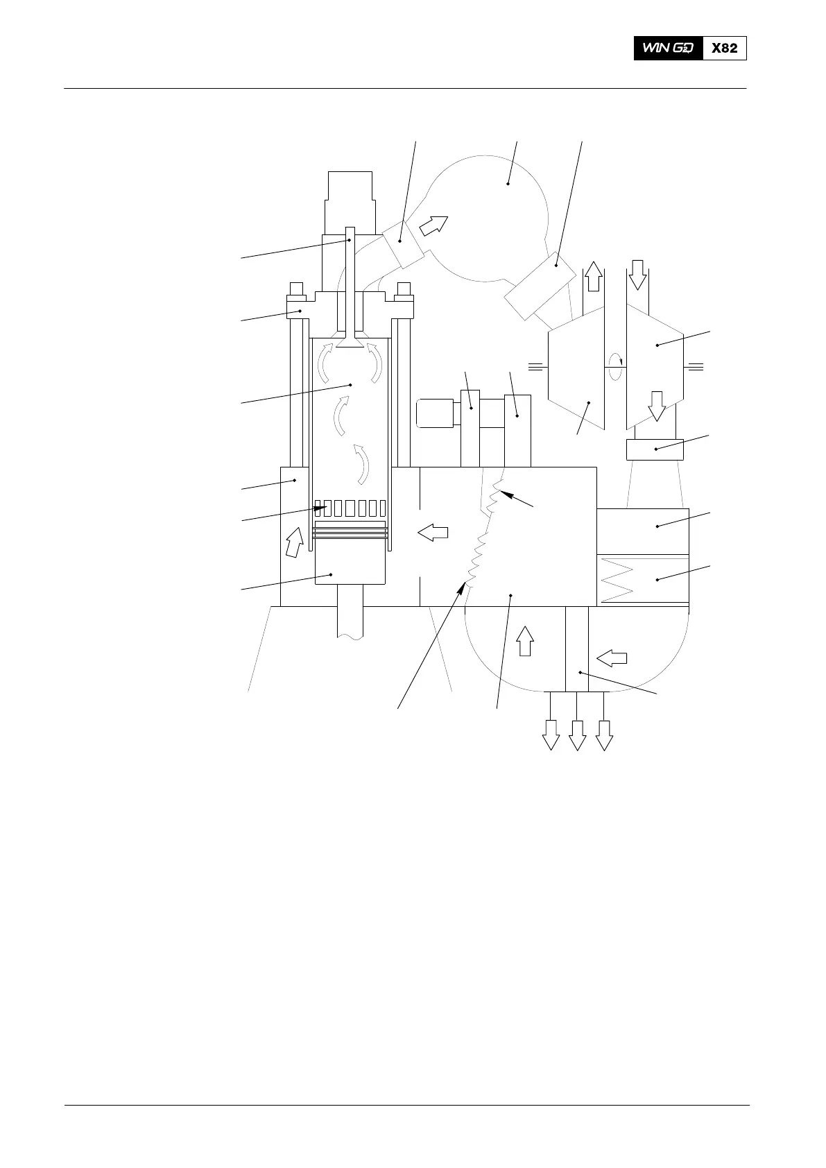
Fig. 1: Schematic Diagram − Turbocharger Operation
1 Exhaust valve 16 Scavenge air cooler
2 Cylinder cover 17 Air duct
3 Cylinder liner 18 Air flaps upstream of auxiliary blower
4 Cylinder jacket
5 Inlet ports
6 Piston EG Exhaust gas
7 Auxiliary blower OW Oily-water drain
8 Air inlet casing EO Exhaust gas, outlet
9 Expansion piece FA Fresh air
10 Manifold PU Piston underside
11 Compressor RS Receiver space
12 Turbine SA Scavenge air (from compressor)
13 Air flaps AS Air space
14 Receiver WD Water drain from water separator
15 Water separator WS Condensate from scavenge air cooler
2014
Turbocharging