Operation
7218−1/A1
Winterthur Gas & Diesel Ltd.
17/ 19
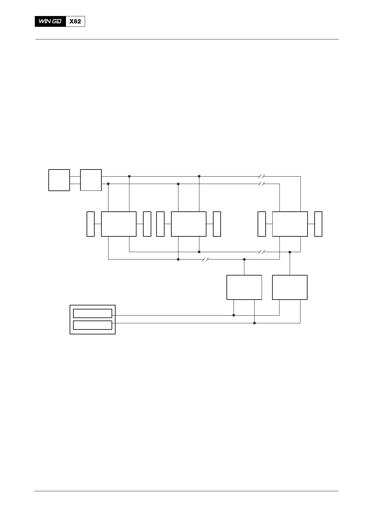
8. Cylinder Lubricating System − Control
8.1 Control System
The WECS−9520 controls the cylinder lubricating system.
The control system includes a row of ALM-20, one ALM-20 for each cylinder (see
Fig. 8). The CAN Bus transmits the signals. To prevent faults one more CAN Bus is
installed and gives redundancy.
The power supply box E85 and the control box E90 supply the necessary power for
the ALM-20. Each ALM-20 has a pressure transmitter to monitor the metering
pressure.
E85 E90
Power supply
DATA FOR 9 CYLINDERS
Crank angle
sensor unit
CAN Bus
SSI Bus
GT5126C
Sensor
Valve
ALM−20
Cyl. 1
ALM−20
Cyl. 2
ALM−20
Cyl. 9
PT3131C
PT3132C
PT3139C
FCM−20
Cyl. 8
FCM−20
Cyl. 9
ZV3131C
ZV3132C
ZV3139C
GT5127C
Fig. 8: Control System
The Flex Control Module(s)−20 (FCM−20) get the necessary data from the last and
next to last cylinders. The SSI Bus transmits the signals from the crank angle sensor
unit. To prevent faults one more SSI Bus is installed and gives redundancy (see
4002−1 Engine Control System WECS-9520).
The 4/2-way solenoid valves operate the lubricating pumps.
2014
Cylinder Lubrication