Operation
8016−1/A1
Winterthur Gas & Diesel Ltd.
9/ 12
BO
HO
SO
OD
46
12
29
1
DT
DT
14
47
5
26
4
23
7
16
18
17
6
15
13
3
43
3037
3042
3032
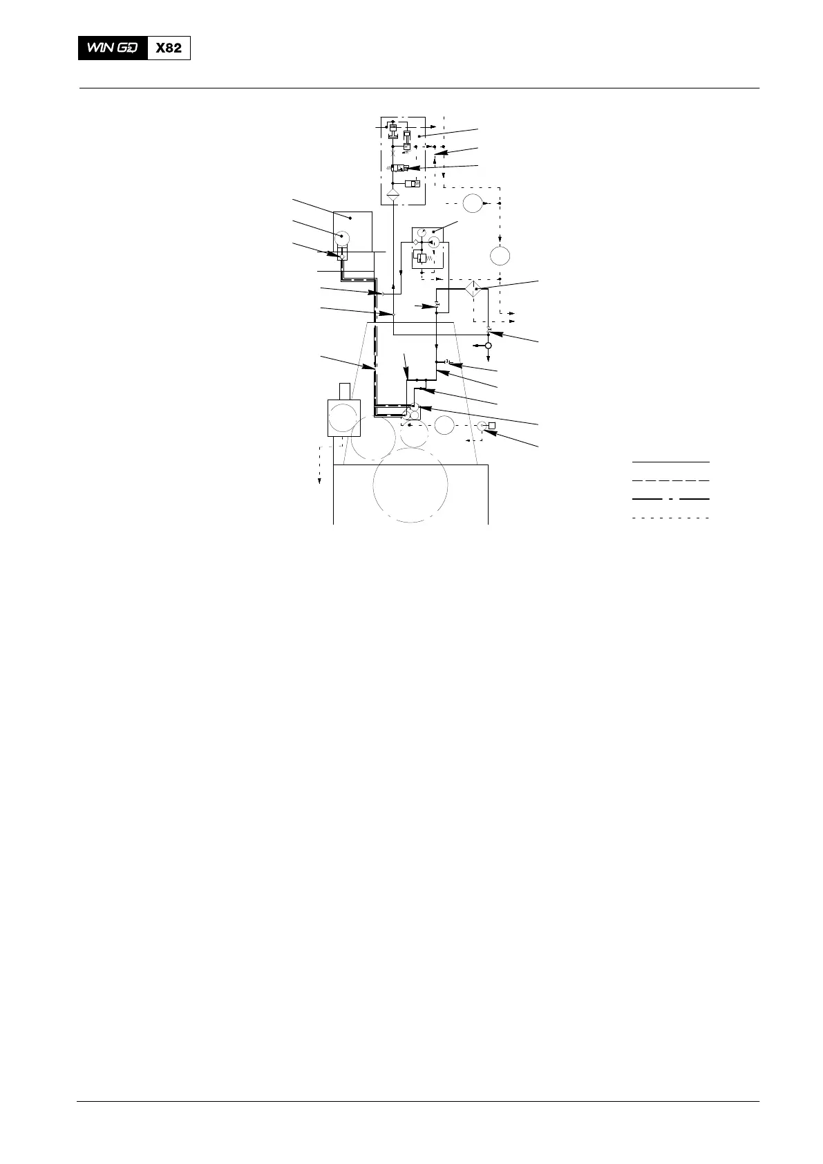
Key to Fig. 3: Servo Oil System
1 Automatic filter 4.20 29 Fuel shut-down pilot valve 3.08
2 Servo pump unit 30 Servo oil return pipe 4.63
3 Servo oil service pump 4.88 31 Drain screw 4.82
4 Servo oil pump 4.15 32 Leakage oil pipe (from HP servo oil pipes)
5 Supply pipe 4.51 33 Flushing oil drain (from automatic filter)
6 HP servo oil pipe 4.55 34 Drain (from fuel pressure control valve 3.06)
7 Servo oil rail 4.11 35 Return from servo oil service pump
8 Exhaust valve control unit 4.10 36 Leakage oil pipe (exhaust valve FE)
9 Hydraulic pipe 4.66 37 Leakage oil pipe (exhaust valve DE)
10 Exhaust valve 4.01 38 Throttle 4.19
11 Injection control unit 3.02 39 Stop valve 4.30−5
12 Fuel pressure control valve 3.06 40 Pressure reducing valve 8.11−1
13 Supply pipe 41 Leakage oil pipe (from hydraulic pipes 4.66)
14 Stop valve 4.37 42 Servo oil return from cylinder lubricating pumps
15 Stop valve 4.80 43 Leakage oil from injection control unit 3.02
16 Non-return valve 4.24−1, 4.24−2 44 Throttle
17 Non-return valve 3.67 45 Servo oil return (from injection control unit 3.02)
18 Non-return valve 4.53 46 Rail unit
19 Flexible hose (inlet) 47 Stop valve (for oil samples)
20 Flexible hose (outlet)
21 Ball valve 3.38
22 Ball valve 3.27 OD Oil drain
23 Level switch LS2055A HO Hydraulic oil
24 Level switch LS2076A BO Bearing oil
25 Leakage inspection point 4.17 DT to oil drain tank
26 Flow sensors FS2061 − FS2062A OI from oil drain tank
27 Stop valve 3.40 SO Servo oil
28 Safety valve 4.23 CL to cylinder lubricating pumps
2014
Lubricating Oil System 6-cylinders to 8-cylinders