Operation
8018−1/A1
Winterthur Gas & Diesel Ltd.
1/ 1
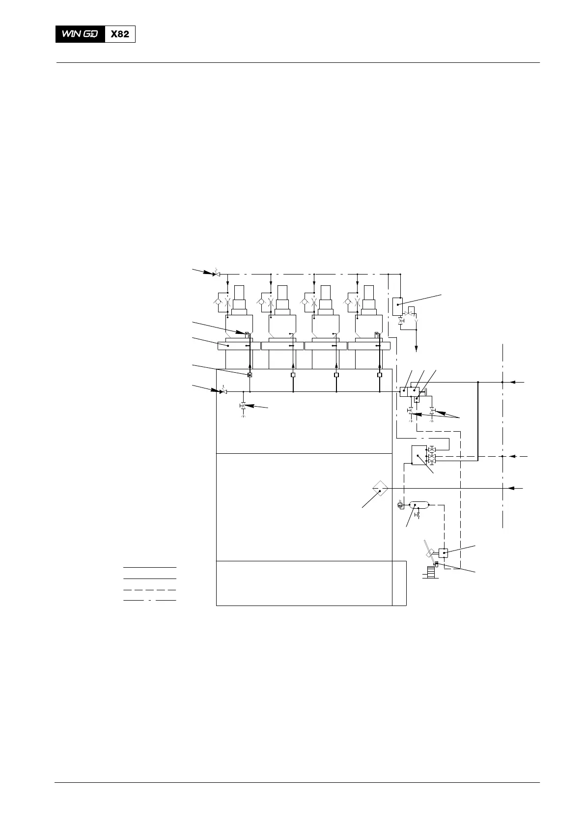
Starting Air Diagram
1. General
The starting air system is shown in the schematic diagram below.
The control air supply unit (6, Fig. 1) and the air bottle (5) supply the air necessary for
engine control.
For more data about the control air system, see 4003−2 Control Diagram and 4003−3
Control and Auxiliary Systems.
You must make sure that the compressed air is clean and dry.
You must open the drain and vent valves (14) at regular intervals to remove
condensation from the starting air system.
ENGINE PLANT
BS
AS
CA
13
7
21
4
8
9
4
AI
BS
CA
12
11
6
5
3
10
SA
WCH01152
14
14
Fig. 1: Schematic diagram − starting and control air
1 Shut-off valve for starting air 11 Turning gear
2 Non-return valve 12 3/2−way valve (on turning gear)
3 Control unit and valve unit for start E 13 Oil leakage (from air spring return)
4 Safety valve 14 Drain and vent valve
5 Air bottle (control air supply A)
6 Control air supply unit A SA Starting air
7 Starting valve CA Compressed air (from board system)
8 Cylinder cover AI Starting air inlet
9 Flame arrester BS Board supply (control air)
10 Automatic fine filter AS Air spring air
2014