Operation
0250−1/A1
Winterthur Gas & Diesel Ltd.
1/ 1
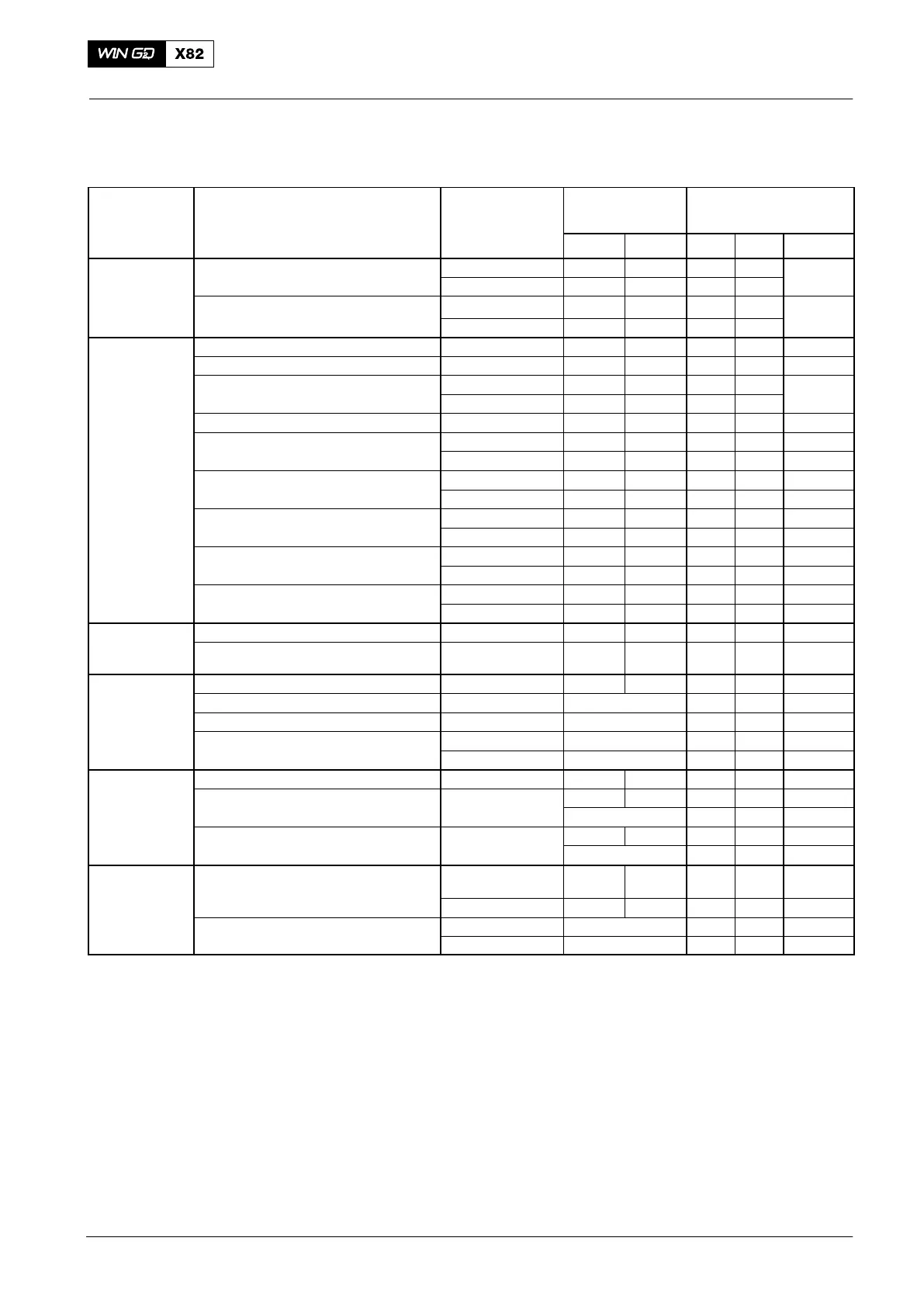
Pressure and Temperature Ranges at Continuous Service
Power MCR
Medium System Location of
Measurement
Gage Pressure
[bar]
Temperature
[_C]
Min. Max. Min. Max. Diff.
Fresh water Cylinder cooling Inlet 3.0 5.0 65 − max.
Outlet each cylinder − − 80 95 15
SAC, low temperature circuit LT Inlet 2.0 4.0 25 36
3)
(single-stage scavenge air cooler) Outlet − − − 80
Lubricating Servo oil Pumps inlet 3.3 5.5 − − −
oil Main bearing Inlet 3.8 5.0 40 50 −
Piston cooling Inlet 3.8 5.0 40 50 max.
Outlet − − − 80 30
Thrust bearing Pads AHEAD − − − 80 −
Torsional vibration damper Supply 3.8 5.0 − − −
(steel spring damper) Damper inlet 2.8
5)
5.0
5)
− − −
Axial vibration damper Supply 3.8 5.0 − − −
(chamber pressure) Monitoring 1.7 − − − −
Turbocharger bearing (ABB, TPL type) Inlet 1.0 2.5 − − −
(with internal oil supply) Housing outlet − − − 110 −
Turbocharger bearing (ABB, TPL type) Inlet 1.3 2.5 − 80 −
(with external oil supply) Housing outlet − − − 120 −
Turbocharger bearing (MHI, MET type) Inlet 0.7 1.5 − − −
Housing outlet − − − 85 −
Fuel Supply unit (fuel pump) Inlet 7.0
1)
10
2)
− 150 −
Downstream of pressure retaining valve
(fuel pump)
Return 3.0 5.0 − − −
Scavenge air Scavenge air cooler after cooler 25 60 −
Intake from engine room (pressure drop) Air filter / silencer max. 10 mbar − − −
Intake from outboard (pressure drop) Ducting and filter max. 20 mbar − − −
Scavenge air cooler (SAC) (pressure drop) new SAC max. 30 mbar − − −
fouled SAC
max. 50 mbar
− − −
Air Starting air Engine inlet 12 25 / 30 − − −
Control air Engine inlet 6.0 7.5 − − −
normal 6.5 − − −
Air spring of exhaust valve Main distributor 6.0 7.5 − − −
normal 6.5 − − −
Exhaust gas Receiver after cylinder − − − 515 Difference
±50
4)
Turbocharger inlet − − − 515 −
Manifold downstream of turbocharger new max. 30 mbar − − −
fouled max. 50 mbar − − −
For the limits of the alarm, slow-down and shutdown signals (see 0250−2).
Pressure measured approximately 6.5 m above crankshaft center line.
(1)
At 100% engine load.
(2)
At stand-by condition; during commissioning of the fuel system, the fuel pressure at
the inlet of the fuel pumps is adjusted to 10 bar.
(3)
The water flow must be in the specified limits (scavenge air cooler specification).
(4)
Maximum temperature difference between the cylinders.
(4)
The value can be different. For the applicable setting value, refer to the
specification of the damper manufacturer.
Operating Data Sheet
2017−04