Home
Xantrex
Controller
XW
Xantrex XW User Manual
5
of 1
of 1 rating
124 pages
Give review
Manual
Specs
To Next Page
To Next Page
To Previous Page
To Previous Page
Loading...
1
3
Table of Contents
Default Chapter
5
About this Guide
5
General Precautions
7
Important Safety Instructions
7
Table of Contents
9
Introduction
17
Purpose
18
Figure 1-1 XW Automatic Generator Start Basic Function
18
System Requirements
19
Functions
20
Features
21
Front Panel
21
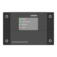
Figure 1-2 XW Auto Generator Start Front Panel
21
Table 1-1 Front Panel Features
21
Bottom Panel
22
Figure 1-3 XW Auto Generator Start Bottom Panel
22
Figure 1-4 Wiring Harness
22
Chapter 2 Installation
23
Preparing an Installation
24
Tools and Materials Required
24
Choosing a Location
24
Routing the Connections
25
Figure 2-1 XW Auto Generator Start External Connections
25
Installing the XW Automatic Generator Start
26
Mounting the Unit
26
Wiring to the 20-Contact Connector
27
Table 2-1 Circuit Limitations
27
Figure 2-2 XW Auto Generator Start Wiring Harness
28
Table 2-2 Required Wiring Size Based on Length of Cable
28
Table 2-3 Contact Numbers and Functions
29
Connecting the Generator
30
Figure 2-3 Type 1 Connection Diagram
31
Table 2-4 Type 1 Relay and Timing Preset Configurations
31
Figure 2-4 Type 2 Connection Diagram
32
Table 2-5 Type 2 Relay and Timing Preset Configurations
32
Figure 2-5 Type 3 Connection Diagram
33
Table 2-6 Type 3 Relay and Timing Preset Configurations
33
Figure 2-6 Type 4 Connection Diagram
34
Table 2-7 Type 4 Relay and Timing Preset Configurations
34
Figure 2-7 Type 5 Connection Diagram
35
Table 2-8 Type 5 Relay and Timing Preset Configurations
35
Figure 2-8 Type 6 Connection Diagram
36
Table 2-9 Type 6 Relay and Timing Preset Configurations
36
Figure 2-9 Type 7 Connection Diagram (Two-Wire)
37
Figure 2-10 Type 7 Connection Diagram (Three-Wire)
37
Table 2-10 Type 7 Relay and Timing Preset Configurations
37
Figure 2-11 Type 8 Connection Diagram (Two-Wire)
38
Figure 2-12 Type 8 Connection Diagram (Three-Wire)
38
Table 2-11 Type 8 Relay and Timing Preset Configurations
38
Figure 2-13 Type 9 Connection Diagram
39
Table 2-12 Type 9 Relay and Timing Preset Configurations
39
Figure 2-14 Type 10 Connection Diagram
40
Table 2-13 Type 10 Relay and Timing Preset Configurations
40
Figure 2-15 Type 11 Connection Diagram
41
Table 2-14 Type 11 Relay and Timing Preset Configurations
41
Figure 2-16 Type 12 Connection Diagram
42
Table 2-15 Type 12Relay and Timing Preset Configurations
42
Figure 2-17 Type 13 Connection Diagram
43
Table 2-16 Type 13 Relay and Timing Preset Configurations
43
Connecting the Thermostats (Optional)
44
Connecting an External Shutdown (Optional)
44
Table 2-17 Wiring for Connecting Thermostats
44
Table 2-18 Wiring for Connecting an External Shutdown
44
Connecting an External Manual ON/OFF Switch (Optional)
45
Connecting an External ON/OFF LED
46
Table 2-19 Wiring for Connecting an External Manual ON/OFF Switch
46
Figure 2-18 External ON/OFF Switch and LED Wiring Diagram
47
Connecting the Wiring Harness to the XW Auto Generator Start
48
Figure 2-19 XW Auto Generator Start External Connections
48
Connecting the XW Auto Generator Start to the Xanbus Network
49
Figure 2-20 Connecting the XW System Control Panel
49
Generator Start
49
Verifying Power Is Available
50
Figure 2-21 Verifying Power Is Available
50
Configuration
51
Overview
52
Figure 3-1 XW System Control Panel Navigation Buttons and XW System Home Screen
52
Chapter 3 , “Configuration” Contains Information and
52
Generator Start
52
Accessing the XW Auto Generator Start Menu
53
Figure 3-2 Accessing the XW Automatic Generator Start Menu
53
The XW Auto Gen Start Menu
54
Figure 3-3 Changing Settings
54
Figure 3-4 XW Auto Generator Start Basic Menu Contents
55
Figure 3-5 XW Auto Generator Start Configuration Menu Contents
56
The Configuration Menu
57
QT en
57
QT Begin
58
QT End
59
Gen Type
59
Table 3-1 Generator Type Descriptions and Examples
59
Cfg Trigger Menu
61
Start DCV 30 Sec
62
Start DCV 15 Min
63
Start DCV 2 Hr
64
Start DCV 24 Hr
65
Stop Float
66
Stop Absorb
66
Temp1
68
Temp2
68
Load
68
Start Load
69
Stop Load
70
Cfg Gen Menu
70
Starter Cool down
71
Gen Cool down
71
Max Run Time
72
Exercise Per
72
Exercise Dur
73
Exercise Time
74
Relay3
74
Gen Run Hold Time
75
Crank Delay
75
Crank Time
75
Crank Retry Time
76
Preheat Time
76
Gen Start Tries
76
Multi-Unit Config
77
Dev Name
77
Dev Number
77
Connections
77
Genmode
78
Automatic Mode
78
Manual on Mode
79
Manual off Mode
80
Restore Defaults
78
Mode
80
The View Device Info Menu
80
View Fault Log
80
View Warning Log
80
View Event Log
81
Table 3-2 Trigger Event Descriptions
81
User Settings
82
Table 3-3 Generator Configuration Settings, Values, Defaults, and User Settings
82
Operation
85
Accessing the XW Auto Generator Start Home Screen
86
Figure 4-1 XW Auto Generator Start Home Screen
86
Starting and Stopping the Generator
87
Figure 4-2 Starting and Stopping the Generator
87
Using Quiet Time
88
Figure 4-3 Using the Quiet Time Feature
88
Modes of Operation
89
Putting the XW Auto Generator Start in Standby Mode
90
Figure 4-4 Changing the Mode to Standby
90
Returning the XW Auto Generator Start to Operating Mode
91
Figure 4-5 Returning the Mode to Operating
91
Troubleshooting
93
Fault Messages
93
Faults and Warnings
93
Faults and Warnings
94
Table 5-1 XW Auto Generator Start Warning Messages
95
Warning Messages
95
Fault Messages
98
Table 5-2 XW Auto Generator Start Fault Messages
98
Electrical Specifications
101
Environmental Specifications
101
Mechanical Specifications
101
Regulatory Compliance
101
Electrical Specifications
102
Figure A-1 XW Auto Generator Start Dimensions
103
Mechanical Specifications
103
Environmental Specifications
104
Regulatory Compliance
104
B Generator Auto Start Requirements and Types
105
Recommended Features
106
Generator Starting Types
106
Two Wire
107
Identification
107
Connection
107
Three-Wire Onan
107
Connection
108
Three-Wire Automotive
108
Identification
108
C Relay Timing
109
Runmode
110
Figure C-1 Runmode Timing Diagram
110
Momentaryrun Mode
111
Figure C-2 Momentaryrun Mode Timing Diagram
111
Glowstop Mode
112
Startstop Mode
112
Figure C-3 Glowstop Mode Timing Diagram
112
Pulsestop Mode
113
Figure C-4 Startstop Mode Timing Diagram
113
Figure C-5 Pulsestop Mode Timing Diagram
114
Figure C-6 Pulsestop Mode Relay 1 Behavior
114
Warranty and Return Information
115
Return Material Authorization Policy
117
Out of Warranty Service
118
Return Procedure
118
Information about Your System
119
5
Based on 1 rating
Ask a question
Give review
Questions and Answers:
Need help?
Do you have a question about the Xantrex XW and is the answer not in the manual?
Ask a question
Xantrex XW Specifications
General
Maximum Power Point Tracking (MPPT)
Yes
Model
XW
Category
Controller
Maximum PV Array Voltage
150V
Nominal Battery Voltage
48V
Output Voltage
48V
Related product manuals
Xantrex C35
114 pages
SOLAR CHARGE CONTROLLER 30
40 pages
Xantrex Trace C Series
56 pages
Xantrex Trace C60
56 pages
Xantrex Trace C35
56 pages