7. Check the minimum pump stroke.
a.
Turn
the oil pump gear
until
the plunger
is at its maximum distance from the
pump body.
b. Using a feeler
gauge,
measure the gap
between the adjusting plate and the
raised
bosson the adjusting puIley.
Minimum pump stroke:
0.2'"
0.25 mm
(0.08'"
0.010 in)
1. Oil
pump
gear 2. Plunger 3.
Minimum
pump
stroke
8. Measure the maximum pump stroke.
a. Pull the oil pump cable
out
of
its sheath
as far as
it
will
go. The cable must be
held in this taut position when
measur-
ing maximum pump stroke.
It
may be
helpful to securely wrap
duct
tape
around the cable where
it
enters the
sheath.
b. Turn the oil pump gear
until
the plunger
is at its maximum distance from the
pump body.
c. Using a feeler
gauge,
measure the gap
between the adjusting plate and the
raised
bosson the adjusting pulley.
Maximum pump stroke:
1.65
-- 1.87 mm
(0.065'"
0.074 in)
1. Oil
pump
gear 2. Plunger 3.
Maximum
pump
stroke 2-5
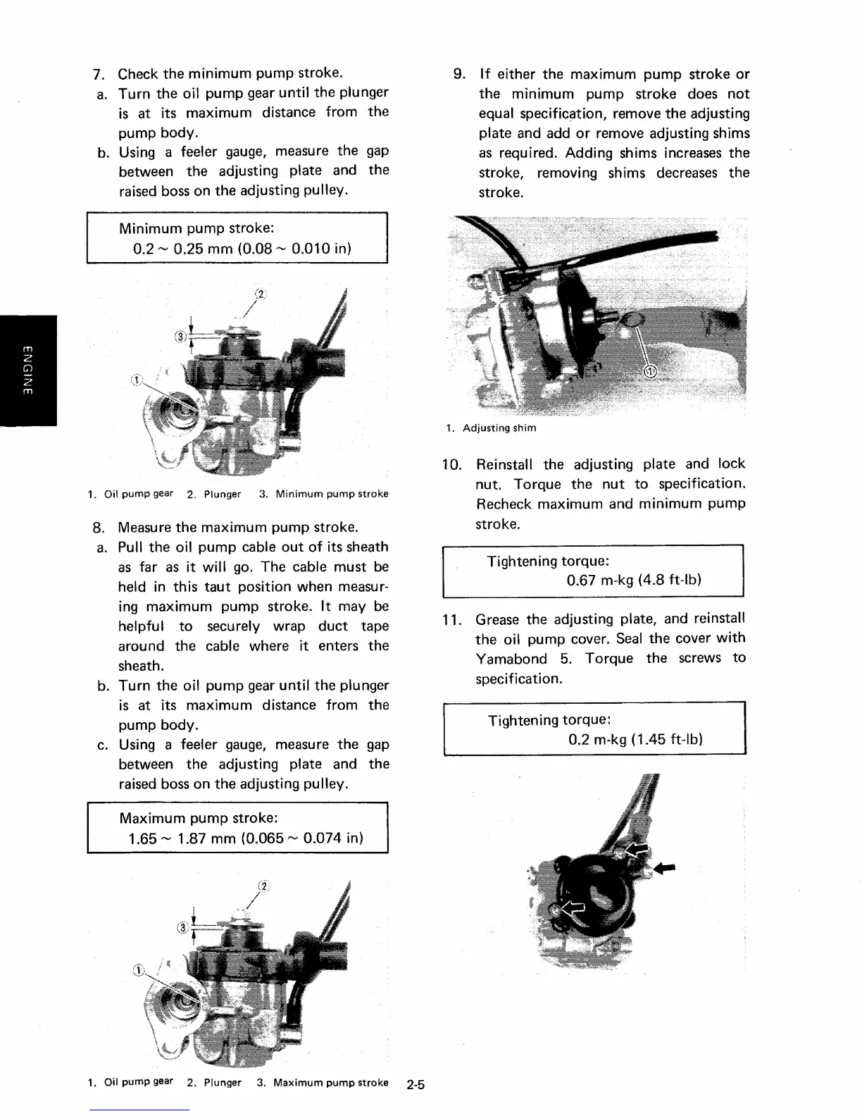
9.
If
either the maximum pump stroke or
the minimum pump stroke does
not
equal specification, remove the adjusting
plate and add or remove adjusting shims
as required. Adding shims
increases
the
stroke, removing shims
decreases
the
stroke.
1.
Adjusting
shim
1
O.
Reinstall the adjusting plate and lock
nut. Torque the
nut
to
specification.
Recheck maximum and minimum pump
stroke.
Tightening torque:
0.67 m-kg (4.8 ft-lb)
11.
Grease
the adjusting plate, and reinstall
the oil pump cover.
Seal
the cover
with
Yamabond 5. Torque the screws to
specification.
Tightening torque:
0.2 m-kg (1.45 ft-Ib)