B. Inspection
1. Check
the
track and clips for cracks,
damage,
or
wear. Replace
the
track
or
clips as required.
2. Inspect
the
sprockets.
If
the
lugs are
excessively worn, replace
the
sprockets.
3. Inspect
the
axle. If it is bent, excessively
scratched, or if
the
splines or threads are
damaged, replace
the
axle.
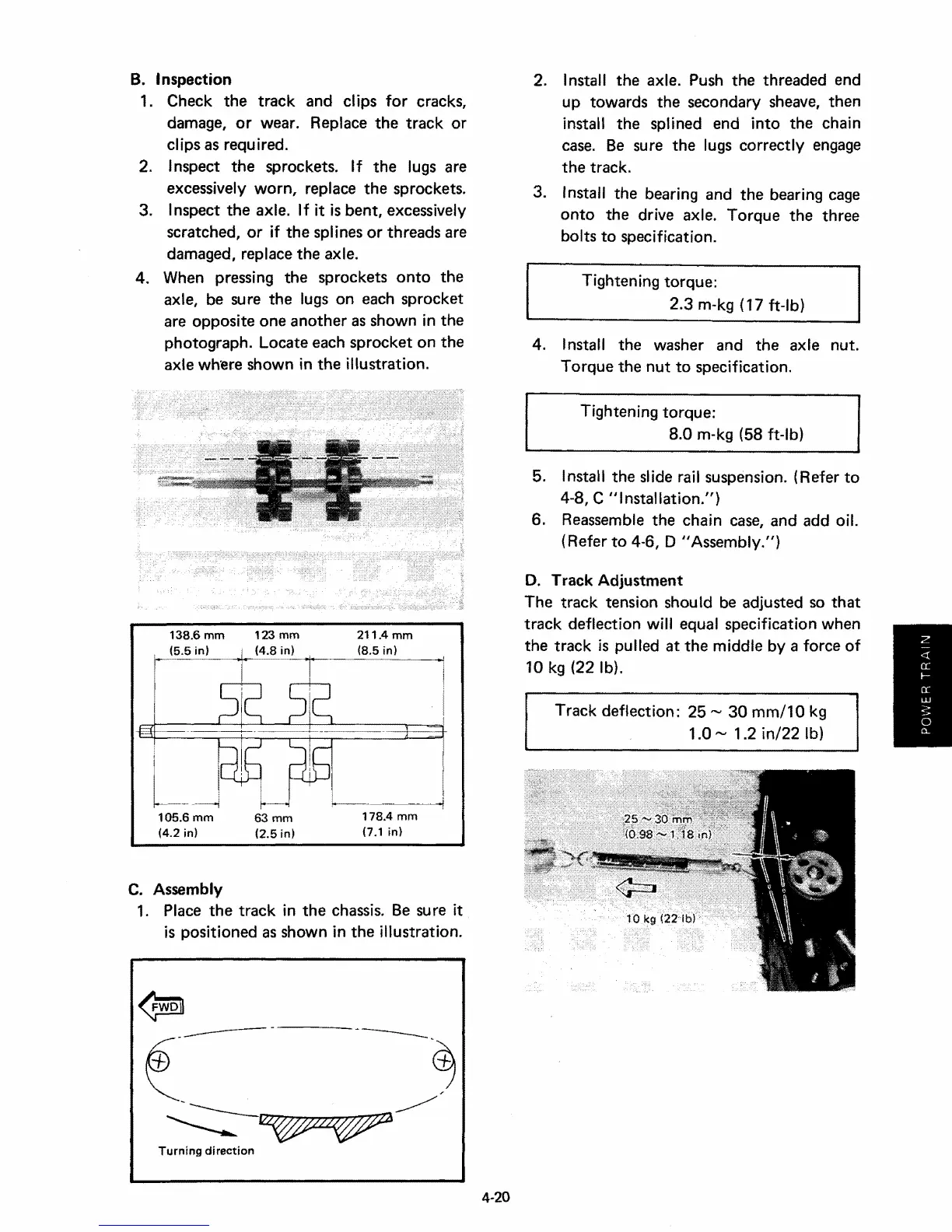
4. When pressing
the
sprockets
onto
the
axle, be sure
the
lugs on each sprocket
are opposite
one
another
as shown in
the
photograph. Locate each sprocket on
the
axle whsre shown in
the
illustration.
2. Install
the
axle. Push
the
threaded end
up towards
the
secondary sheave, then
install
the
splined end into
the
chain
case. Be sure
the
lugs correctly engage
the
track.
3. Install
the
bearing and
the
bearing cage
onto
the
drive axle. Torque
the
three
bolts to specification.
Tightening torque:
2.3 m-kg (17 ft-lb)
4. Install the washer and
the
axle nut.
Torque
the
nut
to specification.
Tightening torque:
8.0 m-kg (58
ft-Ib)
Track deflection: 25,..,
30
mm/10
kg
1.0"" 1.2 in/22 Ib)
5. Install
the
slide rail suspension. (Refer to
4-8, C
II
Installation.")
6. Reassemble
the
chain case, and add oil.
(Refer
to
4-6, D "Assernolv.")
D. Track Adjustment
The track tension should be adjusted so
that
track deflection will equal specification when
the
track is pulled at
the
middle by a force of
10 kg
(22 lb].
178.4 mm
{7.1
in}
211.4
mm
(8,5 in)
63mm
(2.5
in)
138.6
mm
(5.5 in)
105.6
mm
(4.2 in)
~wD\1
~--.
.--~
~~~
Turning
direction
C. Assembly
1. Place
the
track in
the
chassis. Be sure it
is positioned as shown in
the
illustration.
4-20



 To Next Page