5. Inspect
the
drive chain; replace as neces-
sary.
6. Inspect
the
adjusting block. If
the
raised
boss is worn
to
the
base of
the
block,
replace
the
block.
1 Wear
limit
6
mm
(0.24 in)
C. Gearing
Use
the
chart
below
to
change
the
chain case
gearing
to
suit
the
local conditions and
the
rider's driving style.
Higher gearing will increase
the
ma-
chine's
top
speed.
Lower gearing will increase
the
ma-
chine's acceleration and climbing ability.
Do
not
set
the
gearing
to
any of
the
indicated
(X) settings.
~
11T
12T
13T
14T
Driven gear
21T
X
X
X
0
44
S.T.D.
22T
X
X
0 X
44
23T
X
0
X
X
44
24T
0
X
X X
*44
* No. of chain
links
D. Assembly
1. Grease
the
inner surfaces of
the
bearings
and oil seals in
the
chain case.
2. Place
the
brake disc between
the
brake
pads. Be sure
the
raised side
of
the
disc
faces away from
the
chain case.
3. Loosely
bolt
the
chain case in place in
the
chassis. It may be helpful
to
block
up
the
chassis
to
relieve
the
tension on
the
drive axle.
4-12
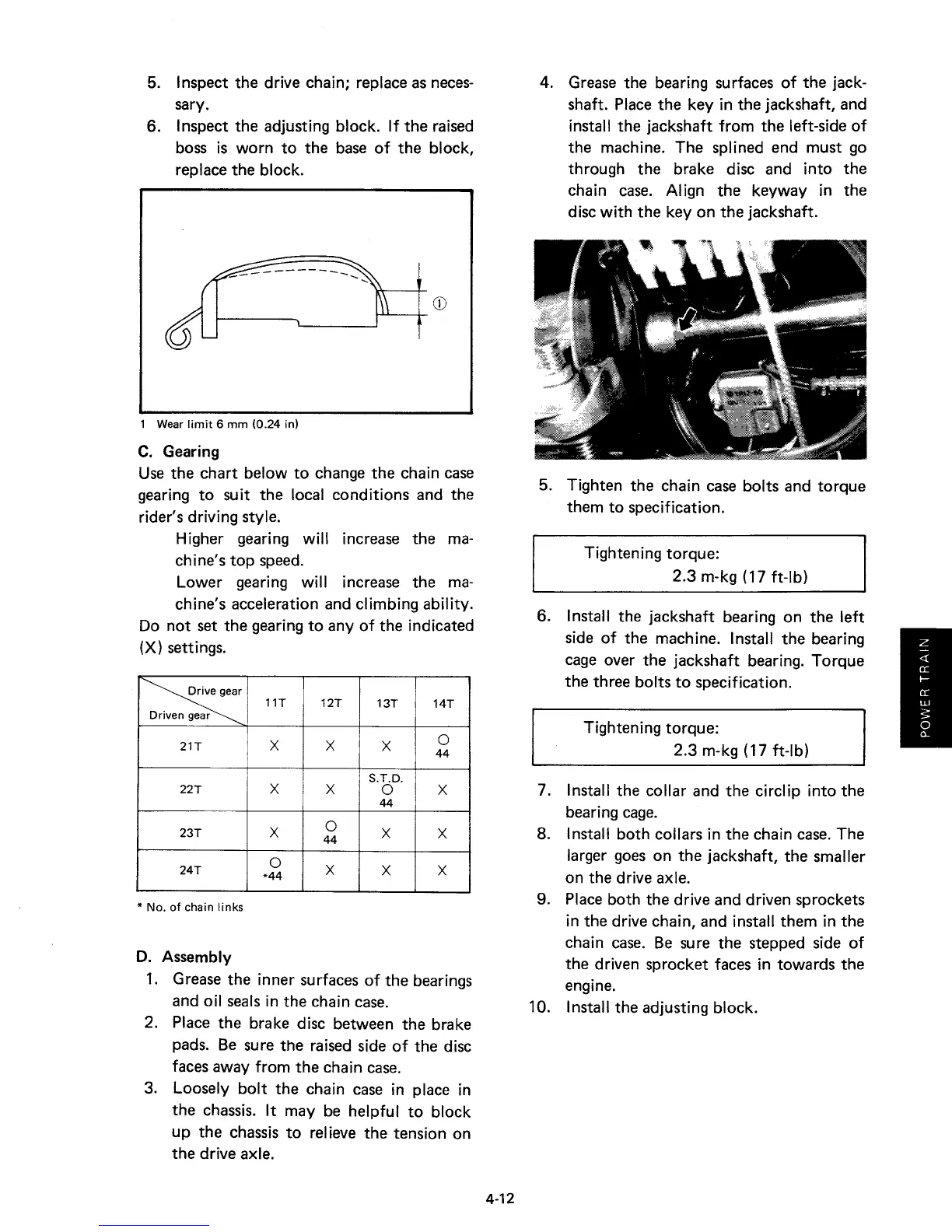
4. Grease
the
bearing surfaces of
the
jack-
shaft. Place
the
key in
the
jackshaft, and
install
the
jackshaft from
the
left-side of
the
machine.
The
splined end must go
through
the
brake disc and into
the
chain case. Align
the
keyway in
the
disc with
the
key on
the
jackshaft.
5. Tighten
the
chain case bolts and
torque
them
to
specification.
Tightening
torque:
2.3
m-kg (17 ft-Ib)
6. Install
the
jackshaft bearing on
the
left
side of
the
machine. Install
the
bearing
cage over
the
jackshaft bearing.
Torque
the
three bolts
to
specification.
Tightening
torque:
2.3
m-kg (17 ft-lb)
7. Install
the
collar and
the
circlip into
the
bearing cage.
8. Install
both
collars in
the
chain case.
The
larger goes on
the
jackshaft,
the
smaller
on
the
drive axle.
9. Place both
the
drive and driven sprockets
in
the
drive chain, and install
them
in
the
chain case. Be sure
the
stepped side of
the
driven sprocket faces in towards
the
engine.
10. Install
the
adjusting block.