B. Inspection
1. Check the brake
pads.
If
either is worn
beyond the wear
limit,
replace the pads
as
a set.
Wear
limit:
1.0 mm (0.04 in)
1. Wear
limit
2.
Replace
any fatigued return spring.
C. Assembly
1. When assembling the brake caliper, be
sure that hooked end
of
each
return
spring is
seated
in the brake arm before
installing the clevis pin. Assemble the
brake as shown in the exploded illustra-
tion. Always usea new cotter pin.
2. Preload the lower spring first, then the
upper spring. Using a pair
of
pliers,
lift
the spring up and over the chain
case.
3. Connect the brake cable to the handle-
bar.
4-15
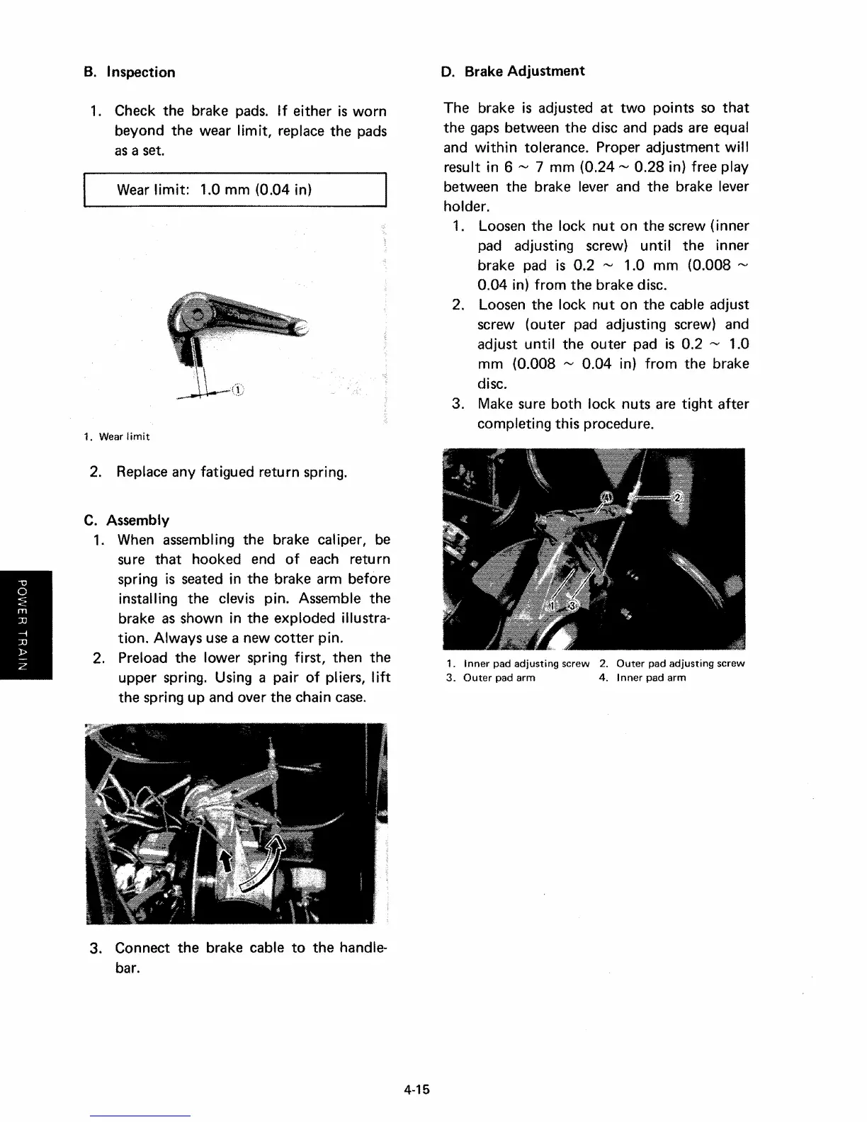
D. Brake Adjustment
The brake is adjusted at
two
points so
that
the
gaps
between the disc and pads are equal
and
within
tolerance. Proper adjustment
will
result in 6 '" 7 mm
(0.24'"
0.28 in) free play
between the brake lever and the brake lever
holder.
1. Loosen the lock
nut
on the screw (inner
pad adjusting screw)
until
the inner
brake pad is
0.2 '" 1.0 mm (0.008 '"
0.04 in) from the brake disc.
2. Loosen the lock
nut
on the cable adjust
screw (outer pad adjusting screw) and
adjust
until
the outer pad is 0.2 '" 1.0
mm (0.008
,...,
0.04 in)
from
the brake
disc.
3. Make sure both lock nuts are
tight
after
completing this procedure.
1.
Inner
pad adjusting screw 2.
Outer
pad adjusting screw
3.
Outer
pad arm 4.
Inner
pad arm