B. Disassembly
1. Carefully remove
the
jets, float, etc.
Never, however, disassemble
the
throttle
valve
or
the
throttle
shaft. The threads
of
the
throttle
shaft have been crimped
so
the
screw will
not
come lose. Once
the
throttle
valve is disassembled, it will
be very difficult
to
reassemble it correct-
ly. The original characteristics of this
carburetor
will be difficult
to
reproduce,
thus
performance will be adversely
affected.
2. CarefuIly clean all parts. Blow
the
jets
and passages clear with compressed air.
Use a
soft
brush
to
clean
the
outside
surfaces so nothing will be scratched or
damaged. Do
not
use a wire
or
any
such
object
to
clear a jet. This will deform
the
jet
and reduce performance.
3. Remove
the
carbon from
the
throttl-e
valve and adjacent area.
Take
care
not
to
scratch
the
throttle
valve
or
bore.
C. Inspection
1. Inspect all jets and passages.
They
must
be clear.
2. Check
the
mating surfaces for wear.
Replace jets as required.
3. Check
the
float valve for damage. If
either
the
float seat or float needle are
damaged, replace
both
parts.
4. Check
the
pilot screw for carbon
deposits; check
the
threads for wear.
Clean and replace
the
jet
as required.
D. Assembly
Use new O-rings when assembling
the
carbure-
tor. Thoroughly grease
the
contact
surfaces of
the
throttle
shaft. Be sure all moving parts in
the
carburetor
operate
smoothly.
1. Install
the
throttle
stop screw with its
spring. For
adjustment
(Refer
to
3-2, E
"Low
Speed Tuning".)
2. Install
the
main
jet
and
the
slow jet.
3. Install
the
slow adjuster with its spring.
For
adjustment
(Refer
to
3-2, E
"Low
Speed Tuning".)
4. Install
the
clip
onto
the
float needle.
5. Hook
the
float needle clip
onto
the
float
tang. Install
the
float, and insert
the
float needle into
the
float valve.
3-2
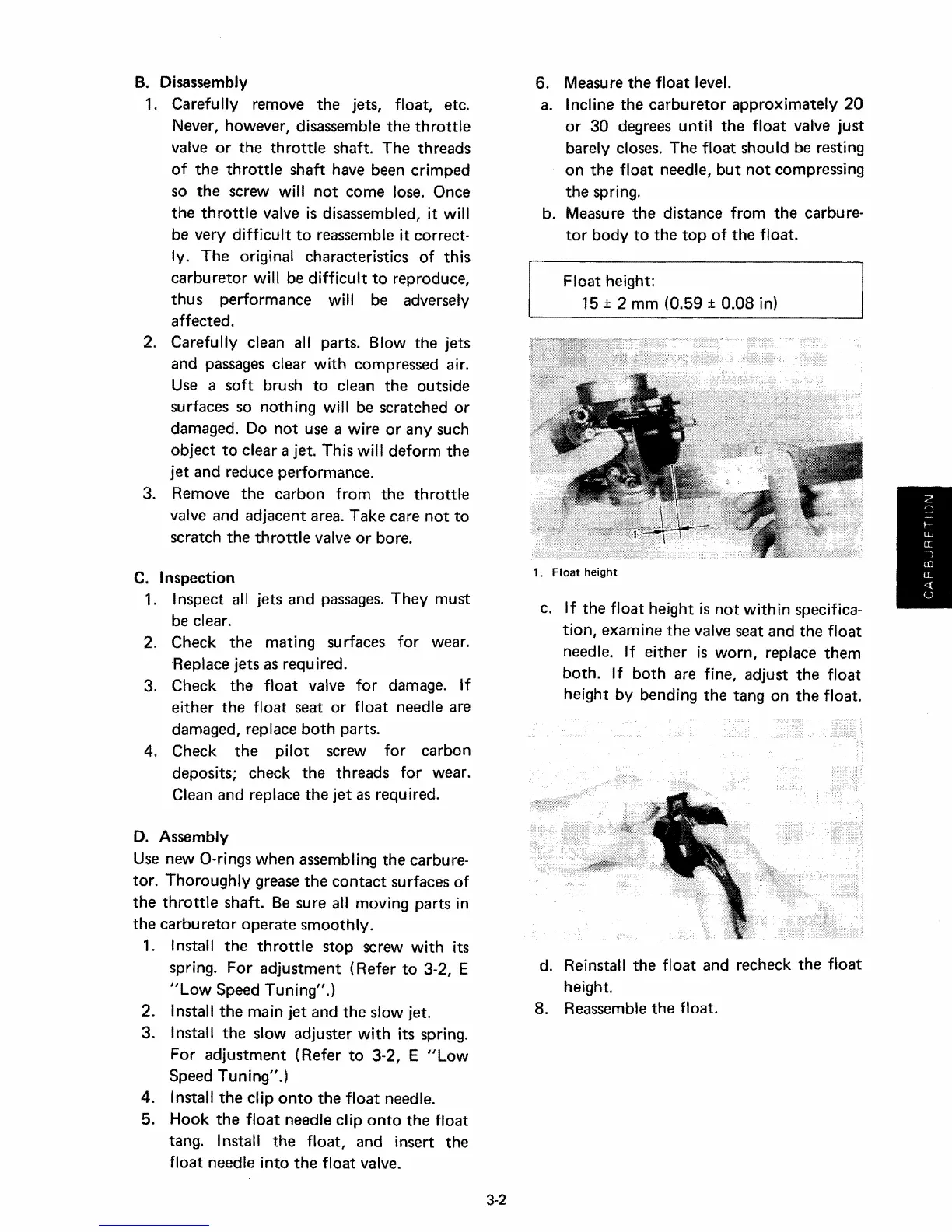
6. Measure
the
float level.
a. Incline
the
carburetor
approximately 20
or
30 degrees until
the
float valve just
barely closes. The float should be resting
on
the
float needle,
but
not
compressing
the
spring.
b. Measure
the
distance from
the
carbure-
tor
body
to
the
top
of
the
float.
Float height:
15 ± 2 mm (0.59 ± 0.08 in)
1.
Float
height
c. If
the
float height is
not
within specifica-
tion,
examine
the
valve seat and
the
float
needle. If either is worn, replace
them
both.
If
both
are fine, adjust
the
float
height by bending
the
tang on
the
float.
d. Reinstall
the
float and recheck
the
float
height.
8. Reassemble
the
float.