7-8
E
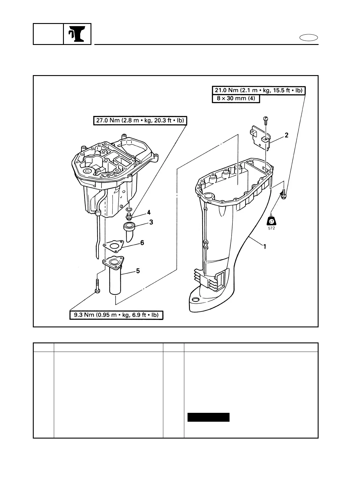
BRKT
UPPER CASE ASSY.
EXPLODED DIAGRAM
REMOVAL AND INSTALLATION CHART
Step Procedure/Part name Q’ty Service points
UPPER CASE ASSY.
DISASSEMBLY
Follow the left “Step” for removal.
1 Upper case 1
2 Baffle plate 1
3 Cap 1
4 Engine oil drain bolt 1
5 Exhaust manifold 1
6 Exhaust manifold gasket 1
Reverse the disassembly steps for instal-
lation.
Not reusable
 Loading...