6C13G11
6-26
1
2
3
4
5
6
7
8
9
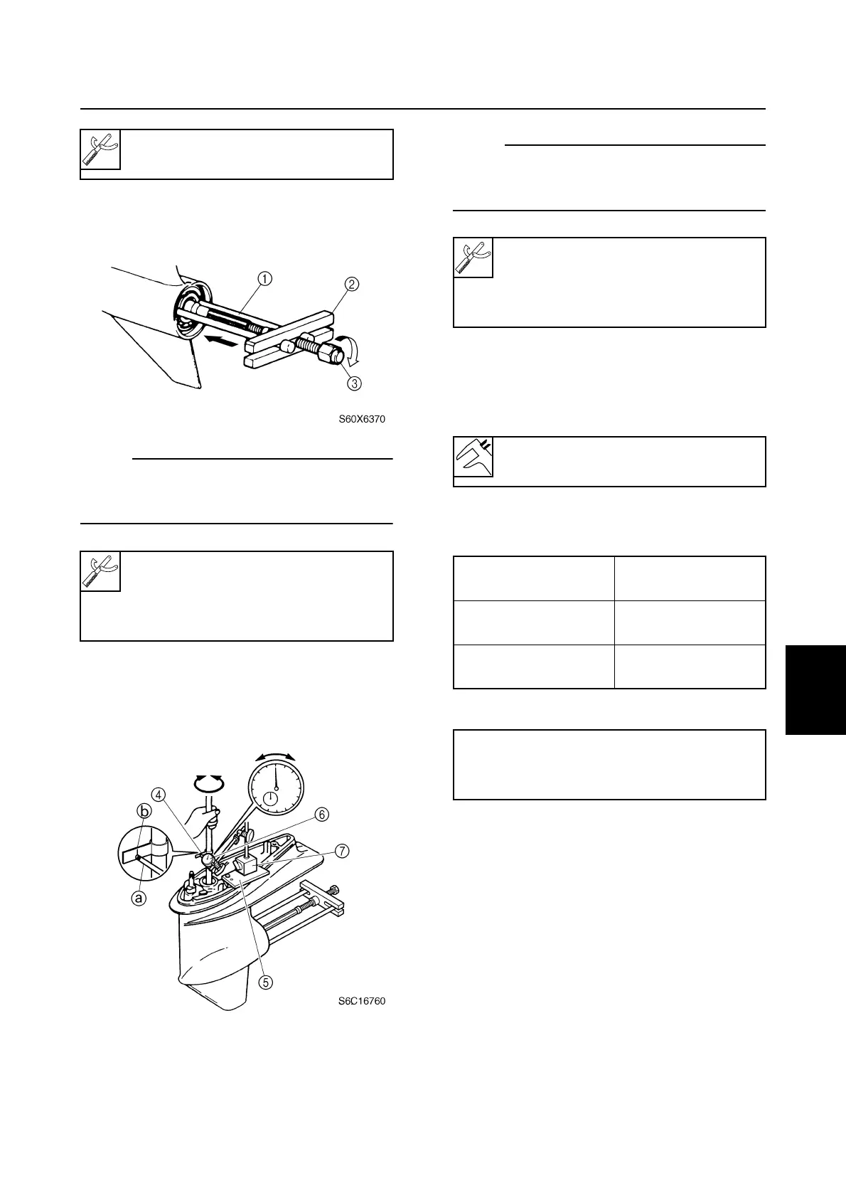
3. Install the special service tools so that it
pushes against the propeller shaft.
NOTE:
Tighten the center bolt while turning the drive
shaft until the drive shaft can no longer be
turned.
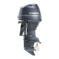
4. Install the backlash indicator onto the
drive shaft (18.0 mm [0.71 in] in diame-
ter), then the dial gauge onto the lower
unit.
NOTE:
Install the dial gauge so that the plunger
a
contacts the mark
b
on the backlash indica-
tor.
5. Slowly turn the drive shaft clockwise and
counterclockwise and measure the back-
lash when the drive shaft stops in each
direction.
6. Add or remove shim(s) if out of specifica-
tion.
M: Measurement
7. Remove the special service tools from
the propeller shaft.
Shift rod push arm: 90890-06052
Bearing housing puller claw S
1
:
90890-06564
Stopper guide plate
2
: 90890-06501
Center bolt
3
: 90890-06504
Backlash indicator
4
: 90890-06706
Magnet base plate
5
: 90890-07003
Dial gauge set
6
: 90890-01252
Magnet base B
7
: 90890-06844
Forward gear backlash:
0.35–0.81 mm (0.0138–0.0319 in)
Forward gear
backlash
Shim thickness
Less than
0.35 mm (0.0138 in)
To be decreased by
(0.58 – M)
×
0.56
More than
0.81 mm (0.0319 in)
To be increased by
(M – 0.58)
×
0.56
Available shim thicknesses:
0.10, 0.12, 0.15, 0.18, 0.30, 0.40, and
0.50 mm
Shimming (F50, F60) / Backlash (F50, F60)