ELEC
Electrical systems
– +
8-13
6C13G11
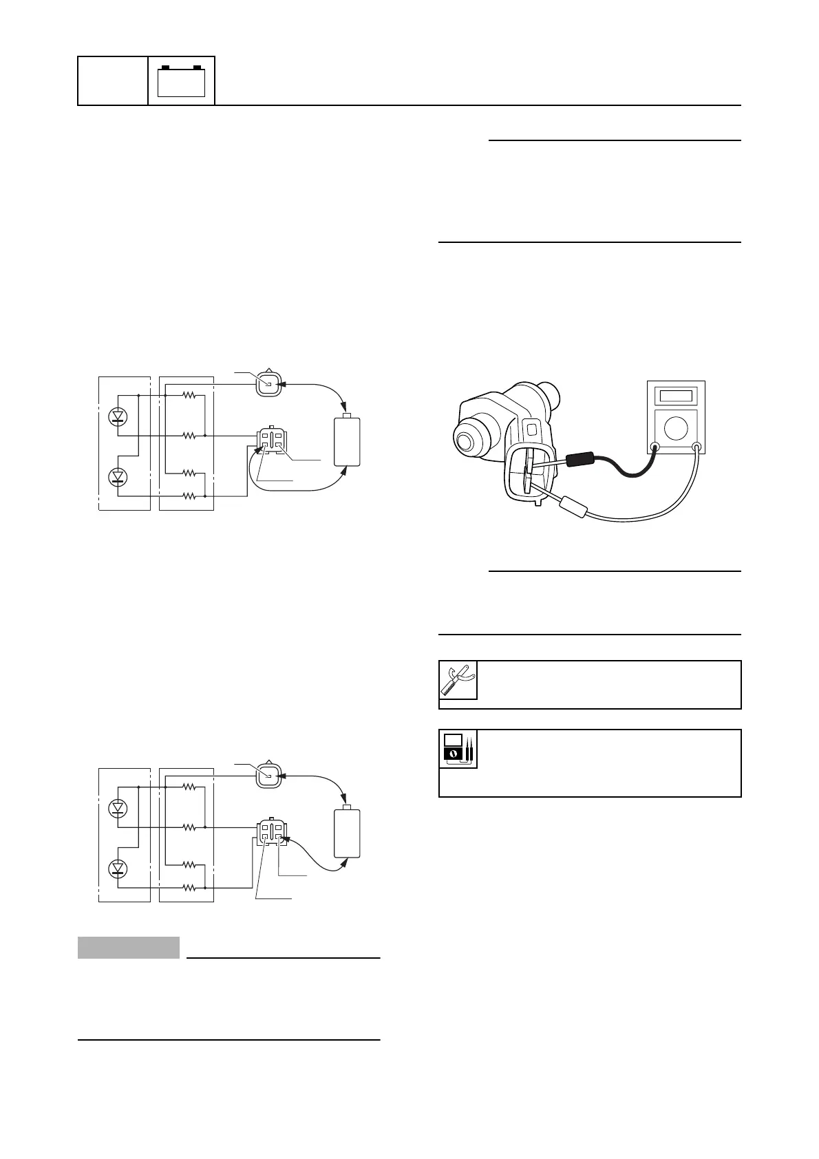
Checking the warning indicators
(tiller handle model)
1. Connect a positive penlight battery termi-
nal (1.5 V) to the yellow (Y) lead.
2. Connect a negative penlight battery ter-
minal (1.5 V) to the pink and white (P/W)
lead.
3. Check that the low oil pressure warning
indicator (LED) comes on. Replace if it
does not come on.
4. Connect a positive penlight battery termi-
nal (1.5 V) to the yellow (Y) lead.
5. Connect a negative penlight battery ter-
minal (1.5 V) to the pink and black (P/B)
lead.
6. Check that the overheat warning indica-
tor (LED) comes on. Replace if it does
not come on.
CAUTION:
Only use a penlight battery (1.5 V) when
checking the LEDs. Other batteries (e.g.,
alkaline batteries or high-voltage batter-
ies) will damage the diodes.
NOTE:
• Do not apply more than 1.7 V to the leads
when checking the LEDs.
• The LEDs only allow current to flow in one
direction. Therefore, if the LEDs do not
come on, reverse the connection.
Fuel control system
8
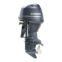
Checking the injectors
1. Measure the resistance of the fuel injec-
tors.
NOTE:
Check the operation of the fuel injectors
using the “Stationary test” of the Yamaha
Diagnostic System.
Checking the electric fuel pump
1. Turn the engine start switch to ON.
2. Listen for the operating sound of the
electric fuel pump
1
. Check the fuel sys-
tem if there is no sound.
S6C18100
+
-
Y
P/W
P/B
S6C18110
+
-
Y
P/W
P/B
Digital circuit tester: 90890-03174
Fuel injector resistance
(reference data):
12.0
Ω
at 21 °C (70 °F)
S6C14170