BRKT
Bracket unit
7-39
6C13G11
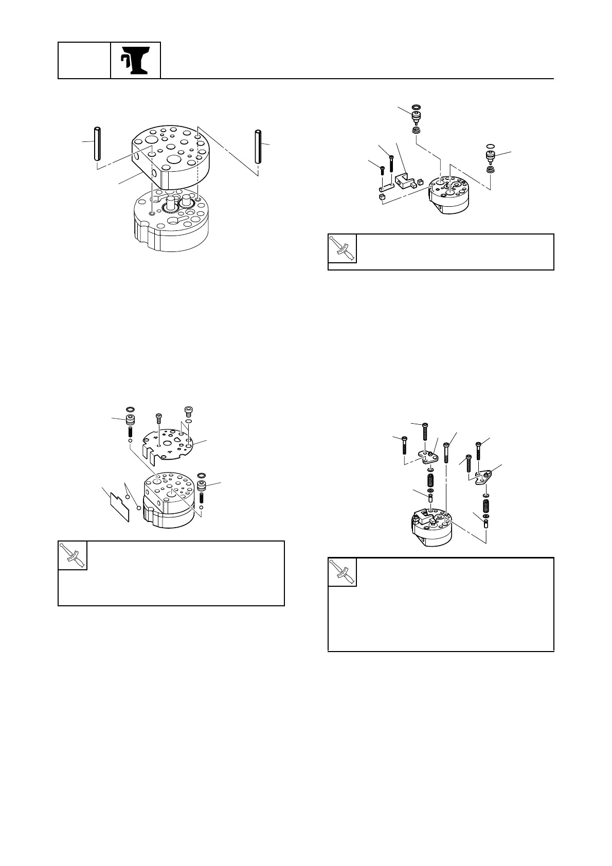
3. Install the gear pump cover
4
, then the
pins
5
.
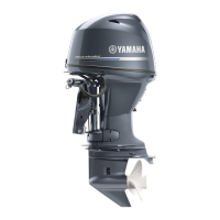
4. Install the adapters
6
into the gear pump
cover.
5. Install the balls
7
into the gear pump
cover with the manual release spring
8
.
6. Install the gear pump bracket
9
by
installing the bolts, and then tighten them
to the specified torques.
7. Install the shuttle pistons
0
, then the
lever
A
.
8. Tighten bolts
B
and
C
to the specified
torque.
9. Install the up-relief valve seat
D
and
down-relief valve seat
E
.
10. Install the relief valve seat caps
F
by
installing bolts
G
and
H
, then tightening
them to the specified torques.
11. Tighten the bolts
I
to the specified
torque.
T
R
.
.
Gear pump bracket bolt (M3):
3 N·m (0.3 kgf·m, 2.2 ft·lb)
Gear pump bracket bolt (M5):
4 N·m (0.4 kgf·m, 3.0 ft·lb)
S6C17620
5
5
4
S6C17630
9
6
6
8
7
Lever bolt (M3)
B
,
C
:
3 N·m (0.3 kgf·m, 2.2 ft·lb)
Relief valve seat cap bolt (M4)
G
:
4 N·m (0.4 kgf·m, 3.0 ft·lb)
Relief valve seat cap bolt (M5)
H
:
5 N·m (0.5 kgf·m, 3.7 ft·lb)
Gear pump housing bolt
I
:
5 N·m (0.5 kgf·m, 3.7 ft·lb)
S6C17640
0
A
C
B
0
S6C17650
E
G
F
H
D
I
G
F
H