Basic Programming 5 - 17
Fig 5.14 Terminal A1 and A2 Analog Inputs Gain Adjustment Example
H3-10 Terminal A2 Gain Setting
H3-11 Terminal A2 Bias Setting
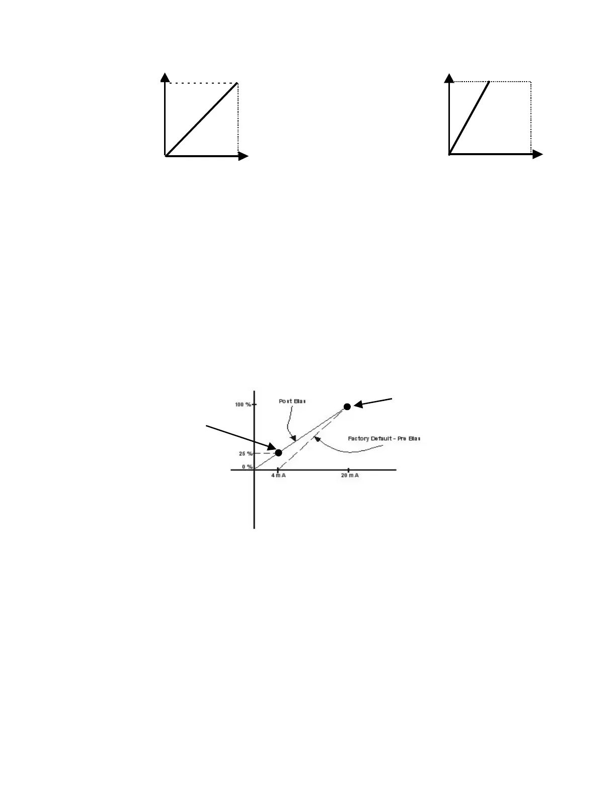
The gain and bias of analog input A2 are adjusted by H3-10 & H3-11 respectively. See the example below:
Problem: A 0-20mA signal is desired for a PI Feedback signal, instead of the factory default 4-20mA signal.
Solution: H3-10 would be unchanged since the top end, 100% feedback, is still equal to 20mA. The Drive needs to have 0mA
equate to 0 % feedback. This is done by setting H3-11=25%.
Fig 5.15 Analog Input Bias Adjustment
Momentary Power Loss Function
L2-01 Momentary Power Loss Detection Selection
L2-02 Momentary Power Loss Ride-thru Time
The Drive allows different responses to momentary power losses. The setting of L2-01 determines whether the Drive will
attempt to restart after a short loss of incoming AC power and for what length of time this capability remains active.
If L2-01=0, the Drive detects a UV1 fault and restarting after any momentary power loss is impossible. The Drive cannot
restart until the external run command is removed and the UV1 fault is reset.
20mA
4mA
0V
10V
H3-02 = 100%
H3-03 = 0%
Output
Frequency
20mA
4mA
0V
10V
H3-02 = 100%
H3-03 = 0%
Output
Frequency
After Gain Applied
Before Gain Applied
200%
H3-02 = 200%
H3-03 = 0%
Output
Frequency
0V
4mA
10V
20mA
H3-02 = 100%
Output
Frequency
H3-03 = 0%
4mA
0V
10V
20mA
H3-10
H3-11