Electrical Installation 2 - 12
Control Wiring
Control Circuit Wire Sizes
For remote operation, keep the length of the control wiring to 50m or less. Separate the control wiring from high-power lines
(input power, motor leads or relay sequence circuits) to reduce noise induction from peripheral devices.
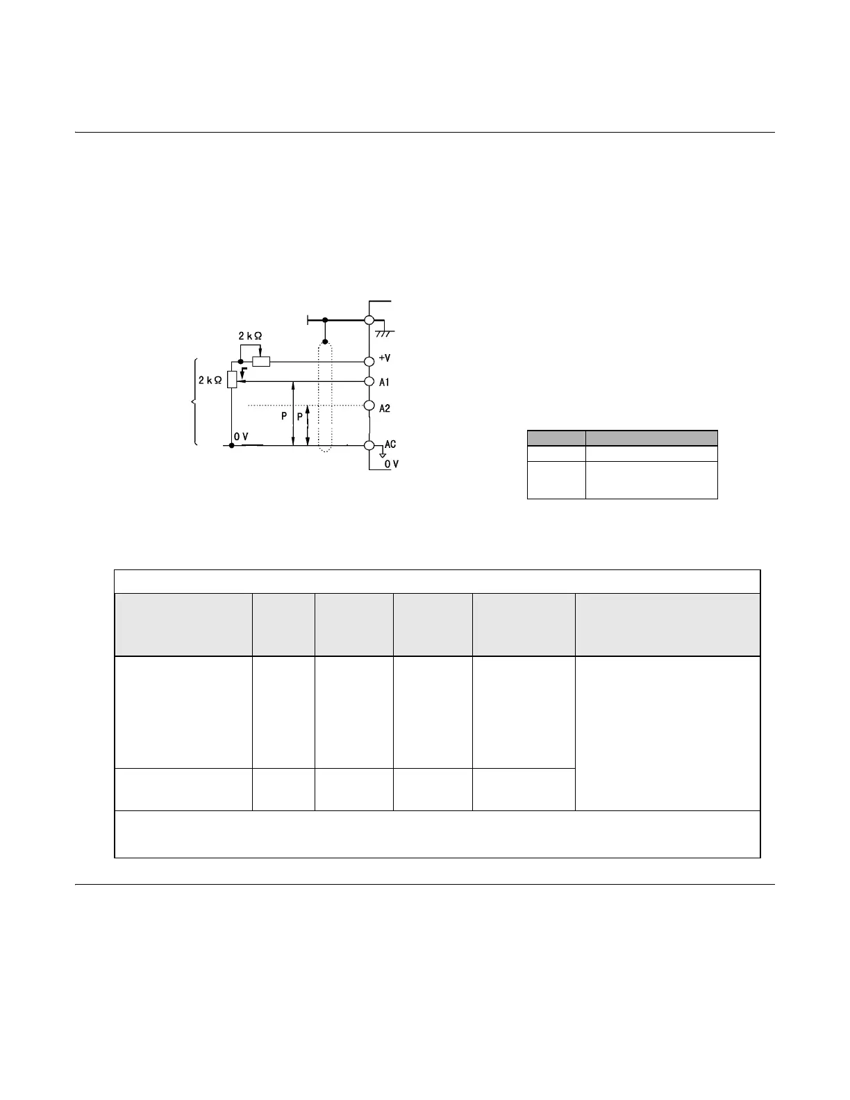
When setting speed commands from an external speed potentiometer (and not from the Digital Operator), use shielded
twisted-pair wires and ground the shield to terminal E(G), as shown in Fig 2.5. Terminal numbers and wire sizes are shown in
Table 2.7.
Fig 2.5 Analog Input Terminal Configuration
Wiring Checks
After all wiring is completed, perform the following checks:
1. Is all wiring correct?
2. Have all wire clippings, screws or other foreign material been removed from the Drive enclosure?
3. Are all terminal screws tight?
Table 2.7 Terminal Numbers and Wire Sizes (Same for all Drives)
Terminals
Te r mi nal
Screws
Tightening
Torque
lb-in
(N•m)
Possible
Wire Sizes
AWG (mm
2
)
Recommended
Wire Size AWG
(mm
2
)
Wire Type
S1, S2, S3, S4, S5, S6, S7
SN, SC, SP, +V, A1, A2,
AC, MI, M2, M3, M4,
MA, MB, MC, FM, AC,
AM, R+, R-, S+, S-, IG
Phoenix
type
*3
4.2 to 5.3
(0.5 to 0.6)
Stranded
wire:
26 to 16
(0.14 to 1.5)
18
(0.75)
• Shielded, twisted-pair wire
*1
• Shielded, polyethylene-covered,
vinyl sheath cable
E(G) M3.5
7.0 to 8.8
(0.8 to 1.0)
20 to 14
(0.5 to 2
*2
)
12
(1.25)
*1.Use shielded twisted-pair cables to input an external speed command.
*2.Yaskawa recommends using straight solderless terminals on digital inputs to simplify wiring and improve reliability.
*3. Yaskawa recommends using a thin-slot screwdriver with a 3.5 mm blade width.
External
frequency
reference
0 to +10 V
4 to 20 mA
Shield terminal
Speed setting power supply, +15 Vdc, 20 mA
Speed command, 0 to 10 Vdc (20 kΩ)
Speed command, 4 to 20 mA (250 Ω)/0 to +10 Vdc (20 kΩ)
Signal Terminal Connections
0-10Vdc A1 to AC
4-20mA
or
0-10Vdc
A2 to AC
E (G)
Trim Potentiometer
(
)