Start Up 4 - 5
DRIVE START UP PROCEDURES
Please review “Drive Start Up Preparation” on page 4-2.
Step
1. Confirm that all three phases are present and that the input voltage is correct for the Drive being set up.
Measure the voltage on the top side of the MCCB/disconnect and record below.
2. If voltage level is within Drive Specification (See Appendix C - Specification), APPLY POWER to energize the
Drive. The STOP, AUTO SEQ and AUTO REF indicators should be on.
3. REMOVE POWER from the Drive. Wait for the Red CHARGE LED (near the power terminals)
to go out.
4. Connect the motor leads to the Drive at terminals U/T1, V/T2 and W/T3.
5. APPLY POWER to the Drive.
6. Press the HAND key once. This puts the Drive in the Hand Mode, allowing run/stop and speed commands by the
digital operator.The AUTO SEQ and AUTO REF indicators turn off. The FWD light turns on. The RUN light turns
on. The STOP light is blinking. “Frequency Ref” (U1-01) is now displayed on the Digital Operator.
7. Press the OFF k e y.
8. Press the MENU key two times. Press the DATA/ENTER key once to enter the Quick Setting Menu. Press the ▼
key 25 times to display parameter E1-01 “Input Voltage”. This parameter selects the nominal input voltage the Drive
will receive. Set this parameter per your application. Press the DATA/ENTER key once. Use the
扶,▼, and 斧 keys
and the DATA/ENTER key to set this parameter per the application.
Ensure the DATA/ENTER key is pressed to enter the selection in the Drive. “Entry Accepted” briefly appears and
the display is now not flashing.
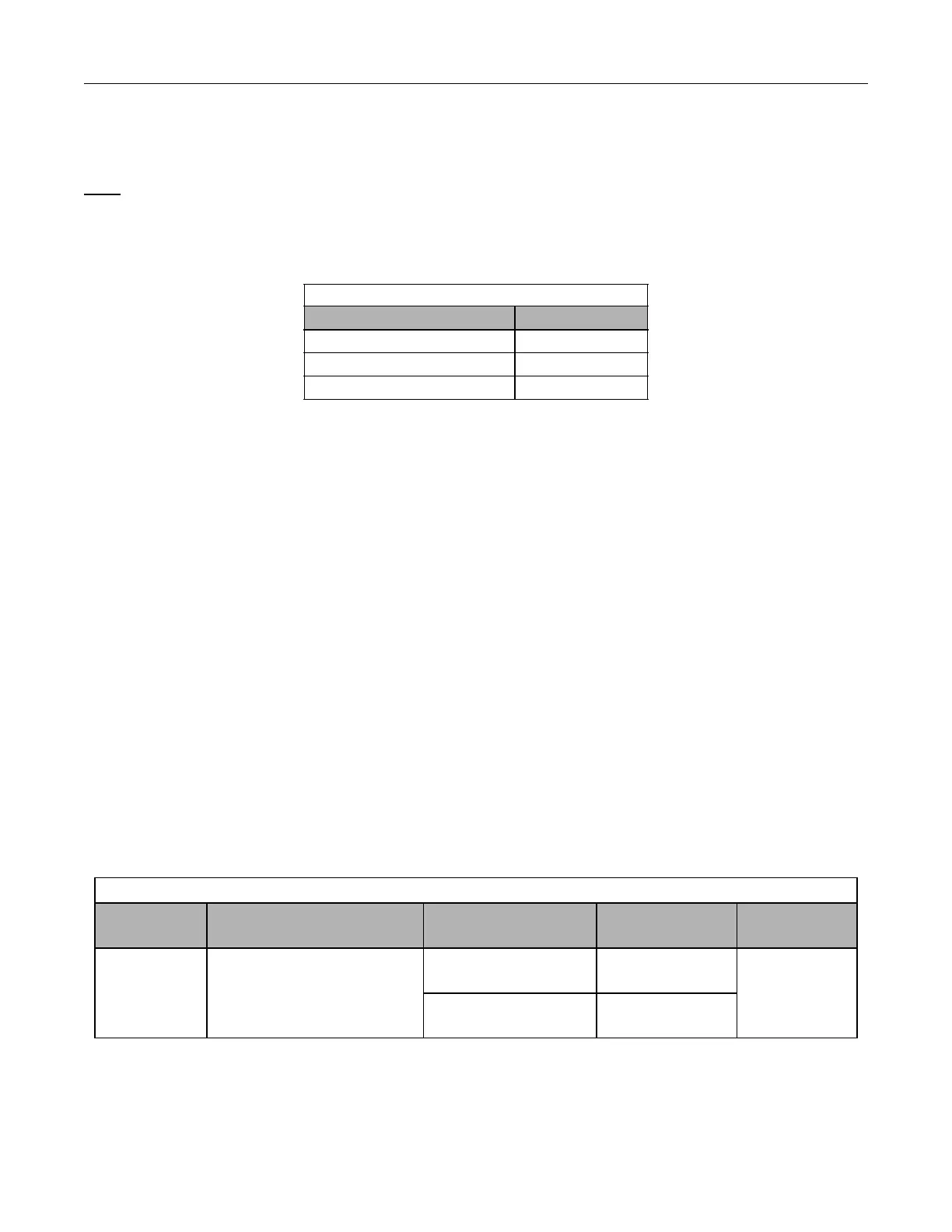
Table 4.1 Input Voltage Check
Measurement Location Voltage (Vac)
L1 – L2
L2 – L3
L1 – L3
Table 4.2 Input Voltage Setting
Parameter
No.
Parameter Name
Digital Operator Display
Setting Range Factory Setting Menu Location
E1-01
Input Voltage Setting
Input Voltage
155.0 to 255.0
(208-240Vac)
230.0
(208-240Vac)
Quick Setting
310.0 to 510.0
(480Vac)
460.0
(480Vac)