Electrical Installation 2 - 13
Control Circuit Terminal Functions
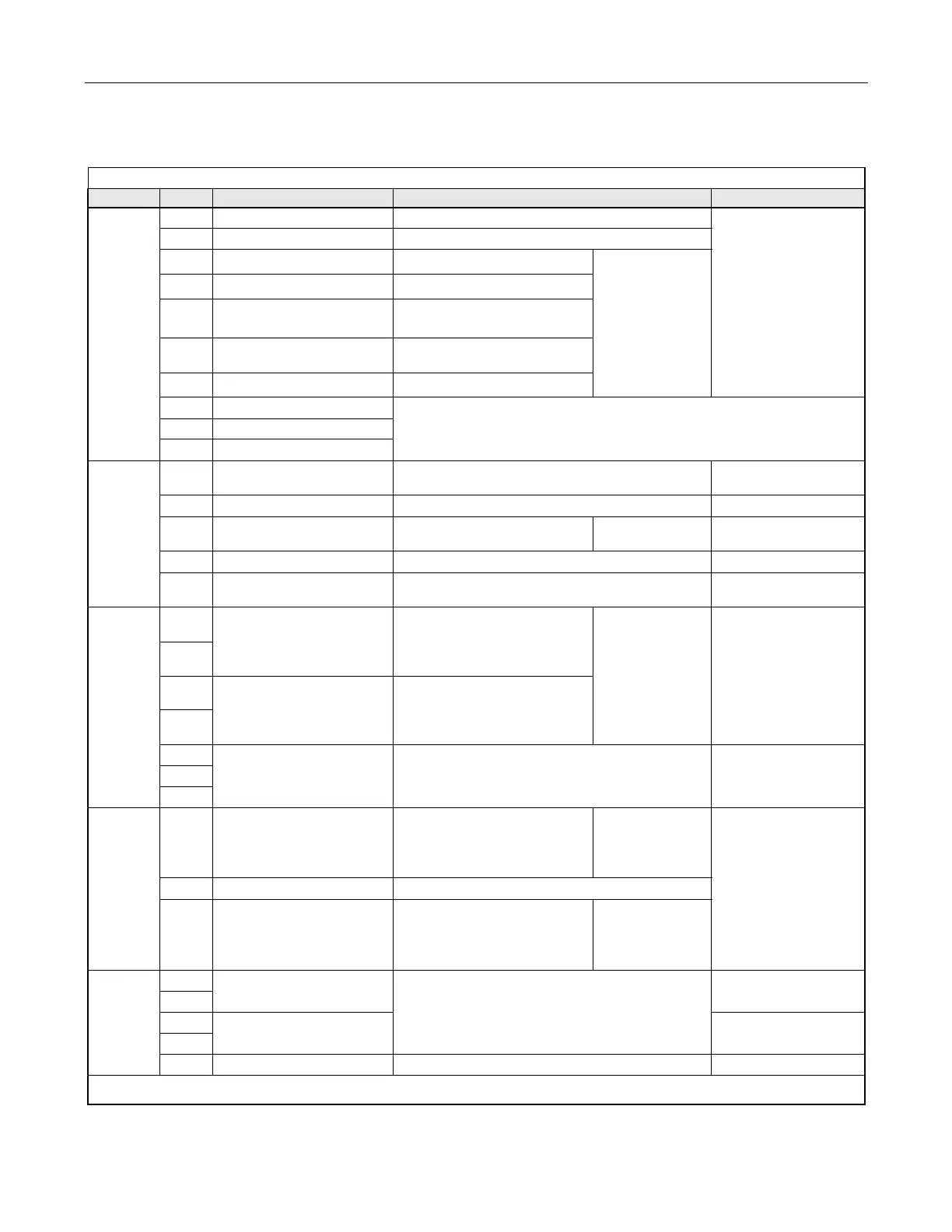
The factory default functions of the control circuit terminals are shown in Table 2.8.
Table 2.8 Control Circuit Terminals
Type No. Signal Name Description Signal Level
Digital
input
signals
S1 Forward run/stop command Forward run when CLOSED; stopped when OFF.
24 Vdc, 8 mA
Photocoupler isolation
S2 Reverse run/stop command Reverse run when CLOSED; stopped when OFF.
S3
External fault input
*1
Fault when CLOSED.
Multi-function
digital inputs
Functions set by
H1-01 to H1-05.
S4
Fault reset
*1
Reset when CLOSED
S5
Multi-step speed reference 1
*1
(Master/auxiliary switch)
Auxiliary frequency reference
when CLOSED.
S6
Multi-step speed reference 2
*1
Multi-step setting 2 when
CLOSED.
S7
Jog frequency reference
*1
Jog frequency when CLOSED.
SN
Refer to Table 2.10 for connection details.
SC Sequence input common
SP
Analog
input
signals
+V +15Vdc power output +15Vdc power supply for analog references
+15Vdc
(Max. current: 20 mA)
A1 Frequency reference 0 to +10Vdc/100% 0 to +10 V(20 kΩ)
A2 Multi-function analog input
4 to 20 mA/100%
0 to +10Vdc/100%
Function set by
H3-09.
4 to 20 mA(250Ω)
0 to +10 V(20kΩ)
AC Analog common – –
E(G)
Shield wire, optional ground
line connection point
––
Digital
output
signals
M1
During Run
(N.O. contact)
CLOSED during operation
Multi-function
digital outputs
Functions set by
H2-01 & H2-02.
Dry contacts
Contact capacity:
1 A max. at 250Vac
1 A max. at 30Vdc
M2
M3
Remote/Auto Operation
(N.O. contact)
CLOSED
M4
MA
Fault digital output signal
(SPDT)
MA/MC: CLOSED during fault condition
MB/MC: OPEN during fault condition
Dry contacts
Contact capacity:
1 A max. at 250Vac
1 A max. at 30Vdc
MB
MC
Analog
output
signals
FM
Multi-function analog output
(output frequency)
0 to +10Vdc/100% frequency
Multi-function
analog monitor 1
Function set by
H4-01
0 to +10Vdc max. ±5%
2 mA max.
AC Analog common –
AM
Multi-function analog output
(output current)
0 to +10Vdc 100% Drive's rated
output current
Multi-function
analog monitor 2
Function set by
H4-02
RS-485/
422
R+
Modbus
communication input
For 2-wire RS-485, jumper R+ and S+ and
jumper R- and S-.
Differential input,
PHC isolation
R-
S+
Modbus
communication output
Differential input,
PHC isolation
S-
IG Signal common - -
*1. The default settings are given for terminals S3 to S7. For a 3-wire sequence, the default settings are a 3-wire sequence for S5, multi-step speed setting 1 for S6 and multi-step
speed setting 2 for S7.