2.2 A: Initialization Parameters
152 YASKAWA TOEPYAIGA5002A GA500 Programming
Table 2.18 Adjustment of Drive Control (Open Loop Vector Control Method)
Adjustment description Parameter Number Possible Solutions Default Recommended Setting
• Torque, increase speed response
• Prevent hunting and oscillation
at middle-range speeds (10 Hz
to 40 Hz)
n2-01 [Automatic Freq Regulator
Gain]
• If torque and speed response are
slow, decrease the setting value.
• If there is hunting or oscillation,
increase the setting value.
1.00 0.50 - 2.00
• Torque, increase speed response
• Prevent hunting and oscillation
C4-02 [Torque Compensation
Delay Time]
*1
• If torque and speed response are
slow, decrease the setting value.
• If there is hunting or oscillation,
increase the setting value.
20 ms 20 ms to 100 ms
• Increase speed response
• Increase speed stability
C3-02 [Slip Compensation Delay
Time]
• When speed response is slow,
decrease the setting value.
• If speed is not stable, increase
the setting value.
200 ms 100 ms to 500 ms
• Improve speed accuracy C3-01 [Slip Compensation Gain]
• If speed is too slow, increase the
setting value.
• If speed is too fast, decrease the
setting value.
1.0 0.5 - 1.5
• Increasing motor excitation
sound
• Prevent hunting and oscillation
at low-range speeds (10 Hz to
or lower)
C6-02 [Carrier Frequency
Selection]
• If there is a loud motor
excitation sound, increase the
setting value.
• If there is hunting or oscillation
at low speeds, decrease the
setting value.
*2
1 - F
• Increase torque and speed
response at low speeds
• Prevent shock during start up
E1-08 [Mid Point A Voltage]
• If the torque and speed response
are slow, increase the setting
value.
• If there is a large shock during
start up, decrease the setting
value.
11.0 V
*3
12.0 V to 13.0 V
*3
E1-10 [Minimum Output Voltage] 2.0 V
*3
2.0 V to 3.0 V
*3
*1 If the value for C4-02 [Torque Compensation Delay Time] is high, the current can increase during start up. Adjust and check the current
during start up.
*2 The default setting changes when the settings for C6-01 [Normal / Heavy Duty Selection] and o2-04 [Drive Model (KVA) Selection]
change.
*3 This is the setting for 200 V class drives. Multiply the voltage by 2 for 400 V class drives.
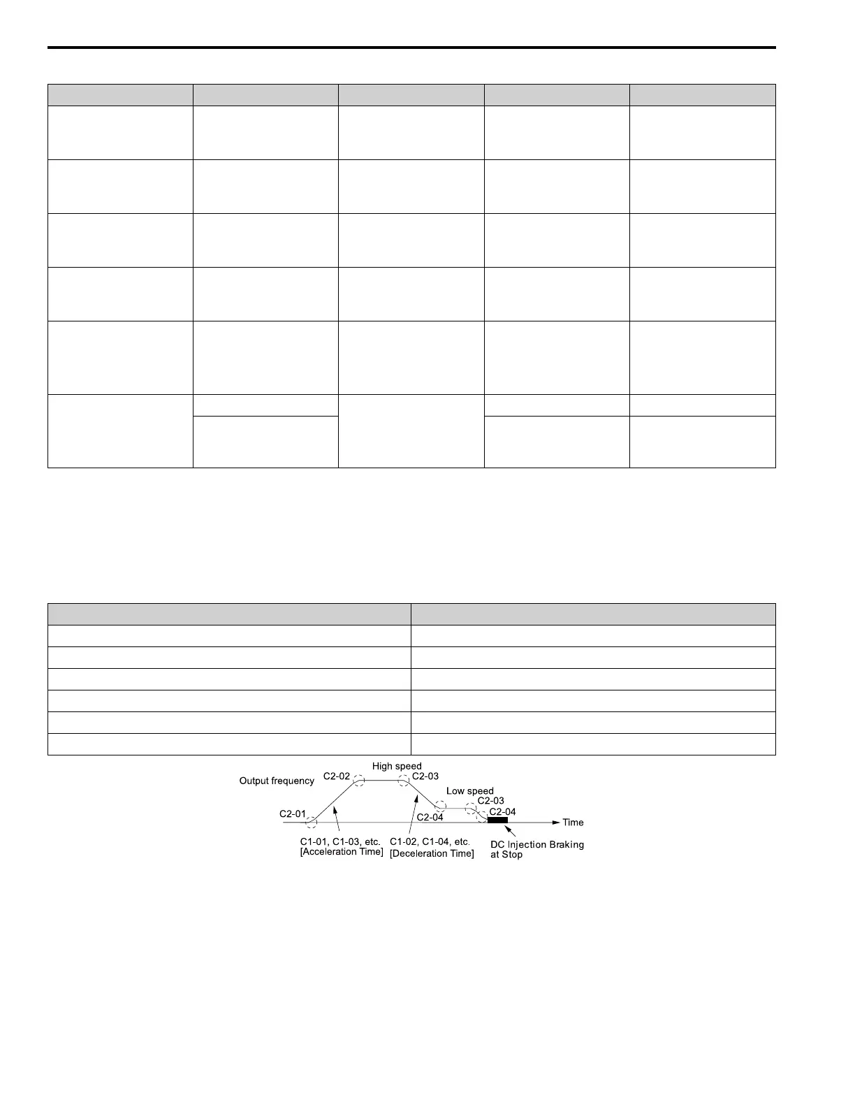
Elevator Start/Stop and Accel/Decel Time Shock Reduction
S-Curve Characteristics, Accel & Decel Time
Adjustment Parameter Name
C1-01, C1-03, C1-05, C1-07 Acceleration Time 1 to 4
C1-02, C1-04, C1-06, C1-08 Deceleration Time 1 to 4
C2-01 S-Curve Time @ Start of Accel
C2-02 S-Curve Time @ End of Accel
C2-03 S-Curve Time @ Start of Decel
C2-04 S-Curve Time @ End of Decel
Figure 2.4 S-curve Characteristics, Accel & Decel Time

 Loading...


