2.3 b: Application
166 YASKAWA TOEPYAIGA5002A GA500 Programming
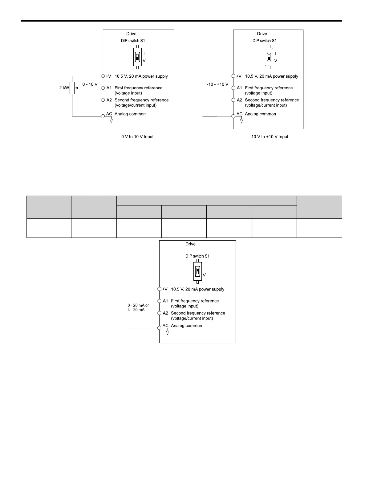
Figure 2.16 Example of Setting the Frequency Reference with a Voltage Signal to Terminal A1
Note:
You can also use this diagram to wire terminal A2.
• Current Input
Refer to Table 2.22 to use a current signal input to one of the MFAI terminals.
Table 2.22 Frequency Reference Current Input
Terminal Signal Level
Parameter Settings
Note
Signal Level
Selection
Function Selection Gain Bias
A2 4 - 20 mA H3-09 = 2 H3-10 = 0
[Frequency Reference]
H3-11 H3-12 Set DIP switch S1 to “I”
for current input.
0 - 20 mA H3-09 = 3
Figure 2.17 Example of Setting the Frequency Reference with a Current Signal to Terminal A2
Changing between Master and Auxiliary Frequency References
Use the multi-step speed reference function to change the frequency reference input between terminals A1 and A2.
2 : Memobus/Modbus Communications
Use MEMOBUS/Modbus communications to enter the frequency reference.
3 : Option PCB
Use a communications option card connected to the drive to enter the Run command.
Refer to the instruction manual included with the option card to install and set the option card.
Note:
If you set b1-15 = 3 but you do not connect an option card, oPE03 [Multi-Function Input Setting Err] will flash on the keypad.
4 : Pulse Train Input

 Loading...


