A failure in the GPD 506/P5 can fall into one of two categories, Alarm or Fault.
A blinking "Alarm" indication is a warning that a drive trouble condition will soon occur, or
that a problem exists in the external circuitry. The drive will continue to operate during an
"Alarm" indication. "Alarm" indications are not entered into the fault register.
A steady "Fault" indication is displayed when the drive’s Fault relay has tripped (drive
shutdown). The motor coasts to a stop, and a fault signal output is present at control
circuit terminals MA, MB, & MC, if parameter n041 is programmed for fault output "Fault"
(" 0 ").
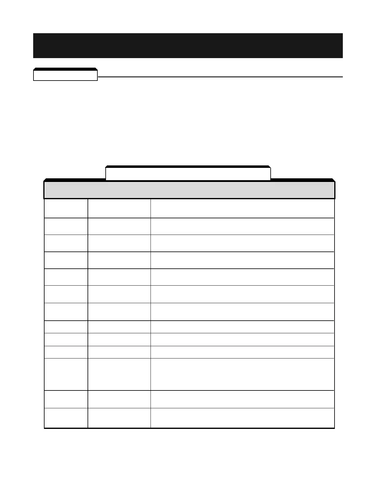
bb External Base Block Base Block command at multi-function terminal is active, shutting off drive
Base Block command output (motor coasting). Temporary condition, cleared when input command is
(blinking) removed.
CALL Communication ready Drive is waiting for the PLC to establish communication (only when
Waiting Message n002 is set for Sequence or Reference from Serial Communications).
(blinking)
CE Modbus transmission Control data cannot be received normally – condition has lasted
Modbus Com Err fault longer than 2 seconds.
(blinking)
EF Simultaneous forward and Fwd Run and Rev Run commands are both closed for more than
Ext Fault reverse operation 0.5 sec. Removing one of the commands will allow drive operation.
(blinking) commands
oH1 Heat sink overheated Fin temperature exceeds 90° C (194° F); drive is programmed for
Overheat 1 operation to continue.
(blinking)
oH3 External overheat External temperature monitoring circuit(s) detected an overtemperature
Overheat 3 condition and produced an input signal. See paragraph 5.19, Data 23.
(blinking)
oL3 Overload Drive output torque exceeds the set Overtorque Detection level
Overload 3 (n078 ); Drive is programmed to continue operation at overtorque.
(blinking)
oPE1
(1)
kVA parameter setting fault kVA setting (n115 ) is incorrect.
KVA Setting Err
oPE3
(1)
Parameter set value fault n036 to n040 (multi-function input) set value fault. See paragraph
MF Input Error 5.19 for description.
oPE5
(1)
Parameter set value fault n011 to n017 (V/f data) set incorrectly.
V/f Error
oPE6
(1)
Parameter set value fault One of the following conditions was detected:
Parameter • n062 > n063 (prohibit frequencies)
Error • n031 < n032 (frequency reference limits)
• n043 = “FV = RST FI MSTR” (“2”) and n036 thru n040 = “Master Fref Sel” (“9”)
• n043 = “FV = RST FI MSTR” (“2”) and n084 ≠ “Disabled” (“0”)
ov Overvoltage Internal monitor of DC Bus voltage indicates that input AC power is
Overvoltage excessively high, while drive is in stopped condition.
(blinking)
Uv Low voltage (Power UV) Internal monitor of DC Bus voltage indicates that input AC power is
Undervoltage below Undervoltage detection level, while the drive is stopped.
(blinking)
NOTES:
(1)
These displays occur only when in the Program mode, when exiting from Program
mode, or when applying power to the drive.
Table 6-1. Alarm Indication and Details
INDICATION
(DISPLAY) PROBLEM DESCRIPTION
6-1
6.1 GENERAL
Section 6. FAULT INDICATION AND TROUBLESHOOTING

 Loading...


