n001
Parameter 0 :
n001
can be read and set; 0 to 9 1 5.23
Selection /
n002
-
n116
read only
Initialization 1 :
n001
-
n035
read and set;
n036
-
n116
read only
2 :
n001
-
n053
read and set;
(Password)
n054
-
n116
read only
3 :
n001
-
n116
read and set
4, 5, 6, 7 : Not Used
8 : 2-Wire initialization
9 : 3-Wire initialization
n002
Operation LED LCD 0 to 8 3 5.16B,
Mode Setting
Setting Sequence
Reference 5.22B
Selection 0 SEQ=OPR REF=OPR Dig. Oper. Dig. Oper.
1 SEQ=TRM REF=OPR Ext. Term. Dig. Oper.
(Oper Mode 2 SEQ=OPR REF=TRM Dig. Oper. Ext. Term.
Select) 3 SEQ=TRM REF=TRM**Ext. Term. Ext. Term.
4 SEQ=OPR REF=COM Dig. Oper. Dig. Oper.
5 SEQ=TRM REF=COM Ext. Term. Ser. Comm.
6 SEQ=COM REF=COM Ser. Comm. Ser. Comm.
7 SEQ=COM REF=OPR Ser. Comm. Dig. Oper.
8 SEQ=COM REF=TRM Ser. Comm. Ext. Term.
n003
Motor Rated Nominal value of input power 150.0 to 255.0 230.0 (VAC) 5.28B
Voltage applied to drive
(230V drive)
(Input 150.0 to 510.0 460.0 (VAC)
Voltage) (460V drive)
150.0 to 733.1 575.0 (VAC)
(600V drive)
n004
Stop Method LED LCD
Setting
Setting
(Stopping 0 Ramp to STOP ** 0 to 3 0 5.25
Method) 1 Coast to STOP
2 Coast w/Timer 1
3 Coast w/Timer 2
Phase LED LCD
n005
Rotation Setting Setting
(Motor 0 Rotate C.C.W ** 0 or 1 0
Rotation) 1 Rotate C.W. (or opposite direction)
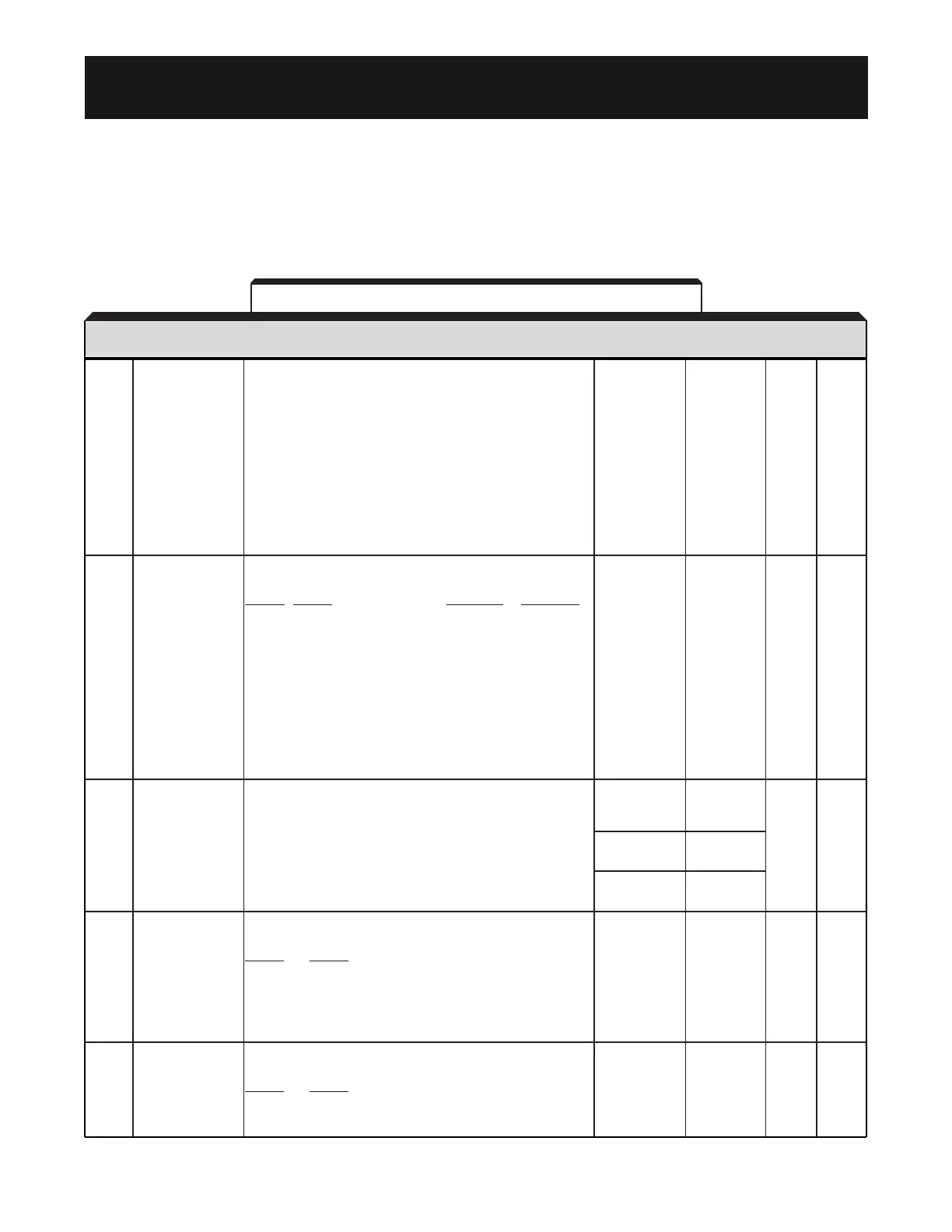
Table A1-1. Drive Parameters (
nXXX
)
PARAM.
FUNCTION NAME SETTING FACTORY USER PARA.
NO. (ACTUAL DISPLAY)
DESCRIPTION
RANGE SETTING ** SETTING REF.
A1-1
Appendix 1. LISTING OF PARAMETERS
The GPD 506/P5 control circuits use various parameters to select functions and characteristics of
the drive. Changing of parameter settings must be done in the Program mode, or by use of the
Quick-Start Displays (see Section 4).
The following table lists all parameters in numerical order. For each parameter, reference
paragraph(s) in Section 5 are listed (if applicable) where the features of the drive affected by that
parameter are described.

 Loading...


