All functions of the GPD 506/P5 are accessed using the Digital Operator. In addition to
controlling motor operation, the operator can enter information into the drive memory to
configure the drive to the application, either by using the Quick-Start Displays or by
entering the Program mode.
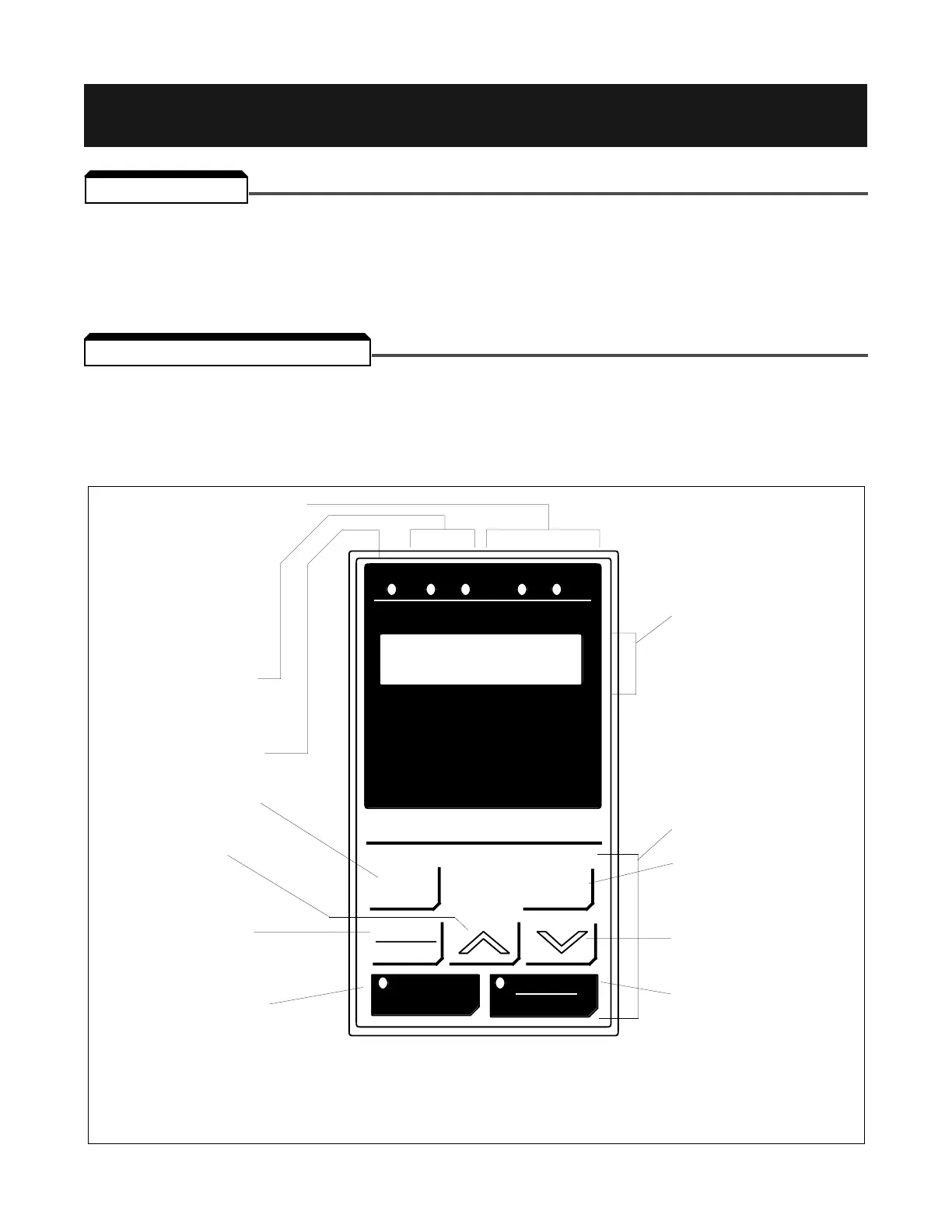
The Digital Operator has a 2-line by 16 character LED display. Both numeric and alpha-
numeric data can appear on the display.
Indicator lamps and keys on the Digital Operator are described in Figure 4-1.
Figure 4-1. Digital Operator
4-1
4.1 GENERAL
4.2 DISPLAY AND KEYPAD
Section 4. DIGITAL OPERATOR
Switch between digital
operator displays *
Increase parameter
number or displayed
value.
Switch between LOCAL
and REMOTE operation
modes.
Run the motor. LED lights
when drive is controlling
motor speed.
* Note that pressing DSPL and ENTER keys simultaneously allows all parameter
data to be read, but not set, while the the drive is running.
KEYPAD SECTION
Displays data to be
changed, and enters new
data. *
Decrease parameter number
or displayed value.
Stop the motor, or reset a
drive fault. LED lights when
drive is in stopped condition.
Indicates which direction
the motor is being
commanded to run.
Lights when the drive
is in Drive (operation) mode.
2 line, 16 character
alphanumeric LCD display;
shows selected operation
status, fault code, or
parameter data.
REMOTE Mode indication LEDs.
The LEDs light when REMOTE
Mode has been selected,
either for Start/Stop (SEQ)
control or Frequency
Reference (REF).

 Loading...


