6-17
A . DIODE MODULE
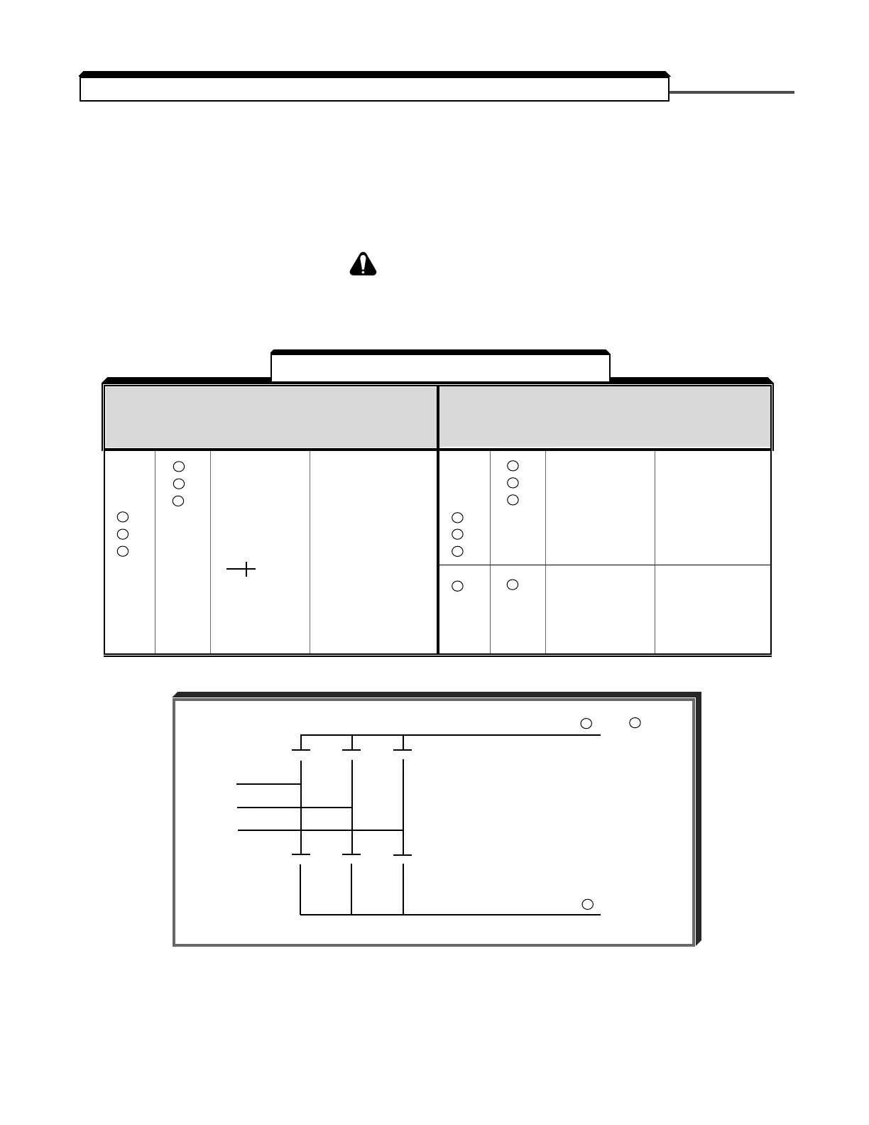
Measure the resistance across the module terminals with a volt-ohm meter. Set the meter
at the X1 range. The measured resistance should be within the values listed in Table 6-4.
NOTE: If the DC bus fuse is blown (PUF), the values shown below may not be accurate.
Power should be removed from L1, L2, & L3 and the CHARGE light
should be out prior to conducting these tests.
RESISTANCE TEST FOR 3Ø CONVERTER MODULES (BRIDGE RECT)
VOM RESISTANCE SCALE R x 1
+ IS THE POSITIVE POLARITY LEAD *
– IS THE NEGATIVE POLARITY LEAD
* The VOM red lead is not necessarily the positive potential in the resistance mode. For these tests the + lead
refers to the positive potential. Make sure you know which polarity you have on your VOM.
+ – NORMAL ABNORMAL
READING READING
ON ON (OHMS) (OHMS)
L1 + 1
L2 + 1
L3 + 1 2.5 to 50 Ω 0 Ω
– L1 or or INFINITE
– L2 0.25 to 0.7
– L3 if using
scale
+ – NORMAL ABNORMAL
READING READING
ON ON (OHMS) (OHMS)
+ – NORMAL ABNORMAL
READING READING
ON ON (OHMS) (OHMS)
L1 –
L2 – LESS
L3 – INFINITE THAN
+ 2 L1 1M Ω
+ 2 L2
+ 2 L3
+ 2 – MAGNITUDE 0 Ω
OF CAP or INFINITE
CHARGE TO
INFINITE
+ – NORMAL ABNORMAL
READING READING
ON ON (OHMS) (OHMS)
▲▲▲
▲▲▲
L
1
L
2
L
3
+ 2 or + 1
–
●
●
●
●
●●
●
Table 6-4. Diode Module Resistances
▲
6.4 DIODE AND IGBT (TRANSISTOR) MODULE RESISTANCE TEST

 Loading...


