B. TRANSISTOR MODULE
Measure the resistance across the module terminals with a volt-ohm meter. Set the meter
to the X1 range. The measured resistance should be within the values listed in Table 6-5.
NOTE: If the DC bus fuse is blown (PUF), the values shown below may not be
accurate.
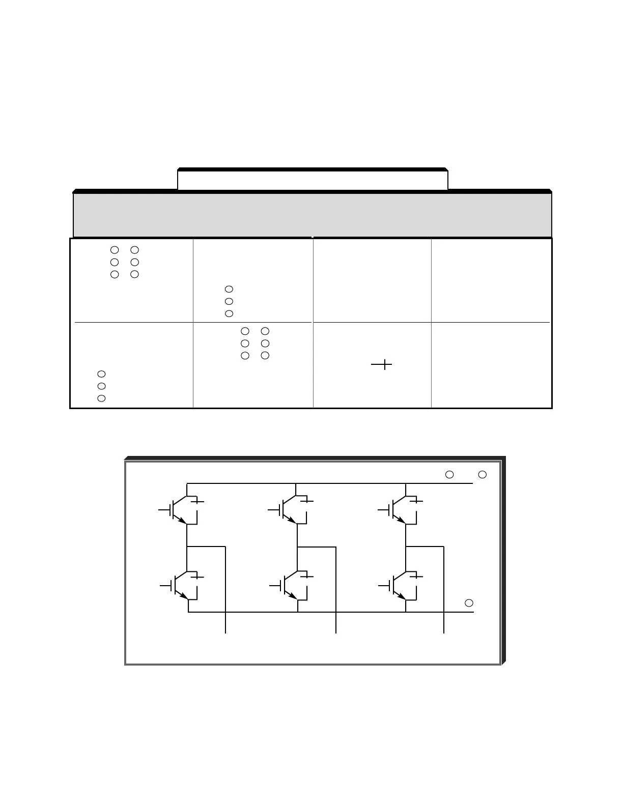
RESISTANCE TEST FOR 3Ø TRANSISTOR MODULES
VOM RESISTANCE SCALE R x 1
+ IS THE POSITIVE POLARITY LEAD *
- IS THE NEGATIVE POLARITY LEAD
* The VOM red lead is not necessarily the positive potential in the resistance mode. For these tests the + lead
refers to the positive potential. Make sure you know which polarity you have on your VOM.
6-18
▲▲▲
▲▲▲
●
●
●
●
●
●
●
T1 or
U
T2 or
V
T3 or
W
B1, + 1 or + 3
–
Table 6-5. Transistor Module Resistances
▲
T1/U
T2/V
T3/W
T1
T2
T3
2.5 to 50 Ω or
0.3 to 0.7 if
using
scale
INFINITE
0 Ω or
INFINITE
0 Ω
NORMAL
READING
(OHMS)
ABNORMAL
READING
(OHMS)
–
–
–
B1/ + 3/ +1
B1/ + 3/ +1
B1/ + 3/ +1
T1/U
T2/V
T3/W
T1/U
T2/V
T3/W
–
–
–
B1/ + 3/ +1
B1/ + 3/ +1
B1/ + 3/ +1
+
ON
–
ON

 Loading...


