2-1
• Verify wires are properly connected and no erroneous grounds exist.
• Remove all debris from the drive enclosure. Check for loose wire clippings.
• Verify all mechanical connections inside the drive are tight.
• Verify motor is not connected to load.
• Apply input power only after the front cover is in place. DO NOT remove the front cover
or Digital Operator while input power is on.
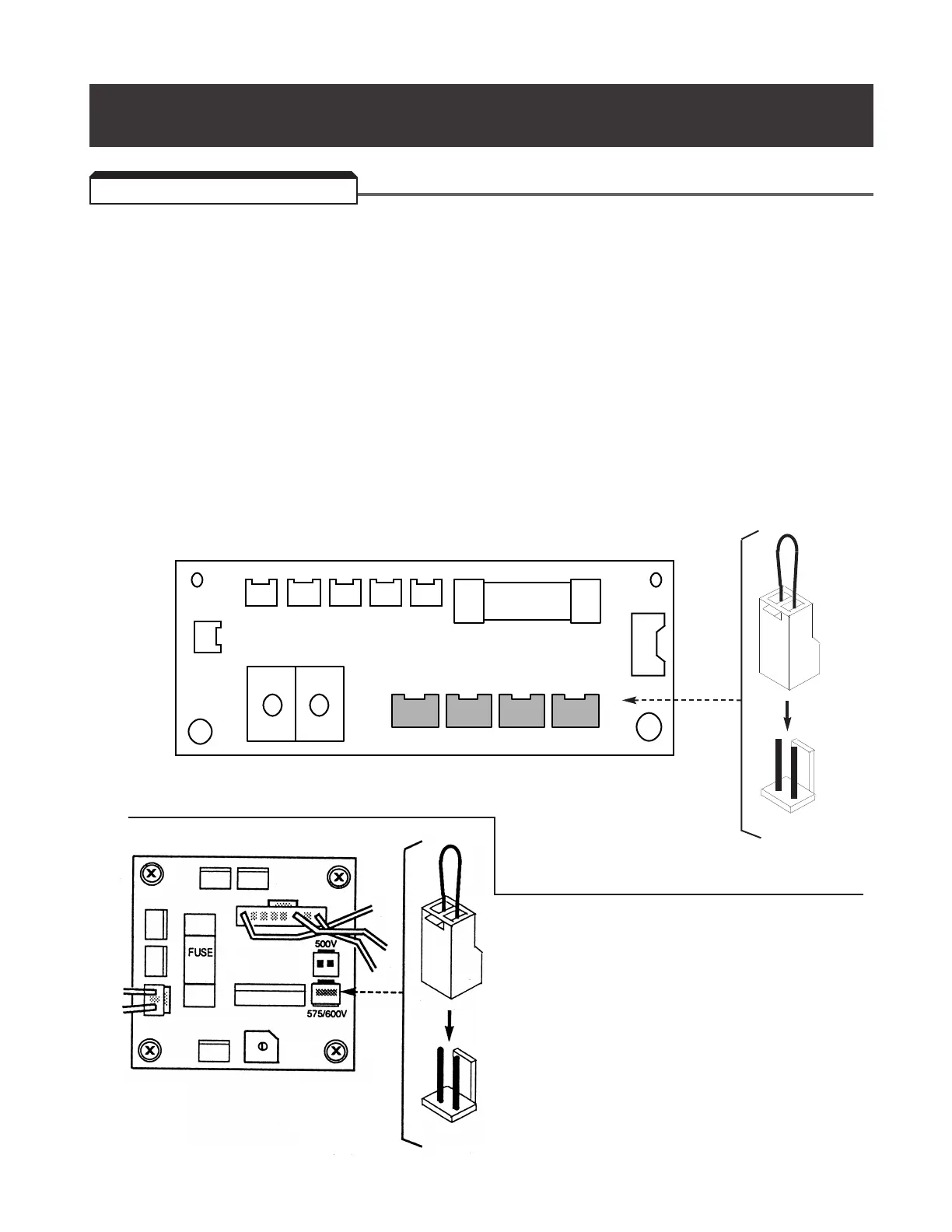
• For 460V, GPD506V-B041 thru -B096 (CIMR-P5M40181F thru 40451F):
Verify that the drive power voltage select connector, located at lower left corner inside
drive chassis (see Figure 2-1), is positioned correctly for the input power line voltage.
Voltage is preset to 460V at the factory. Reposition, if required, to match nominal line
voltage.
23CN 24CN 25CN 26CN 22CN FU2
21CN
sr
TB1
++
380V 400/415V 440V 460V
20CN
•
•
•
•
Figure 2-1a. Power Voltage Selection in 460V drive
2.1 PRE-POWER CHECKS
Section 2. INITIAL START-UP ("LOCAL" CONTROL)
For 600V CIMR-P5M50181F thru
51600F. Verify that the drive power
voltage select connector, located at
lower left corner inside drive chassis
(see Figure 2-1b), is positioned
correctly for the input power line
voltage. Voltage is preset to 575/600V
at the factory. Reposition, if required, to
match nominal line voltage.
Figure 2-1b.
Power Voltage Selection
in 600V Drive

 Loading...


