• After completing the start-up, connect the motor to the load.
• Additional control circuit wiring can be added, and parameters in the drive can be
programmed to configure the drive system to your specific application, including “Remote”
(2-wire or 3-wire) Control. (See Table 5-1 for listing of Programmable Features
descriptions.)
The drive uses internal NV-RAM to store information when power is removed or in the event
of a power failure. Therefore, when power is reapplied, operation will begin at the same
state as when power was removed.
The following information is stored:
1. Last frequency command setting from Digital Operator.
2. The sequence of failure conditions that occurred before power was removed.
2-4
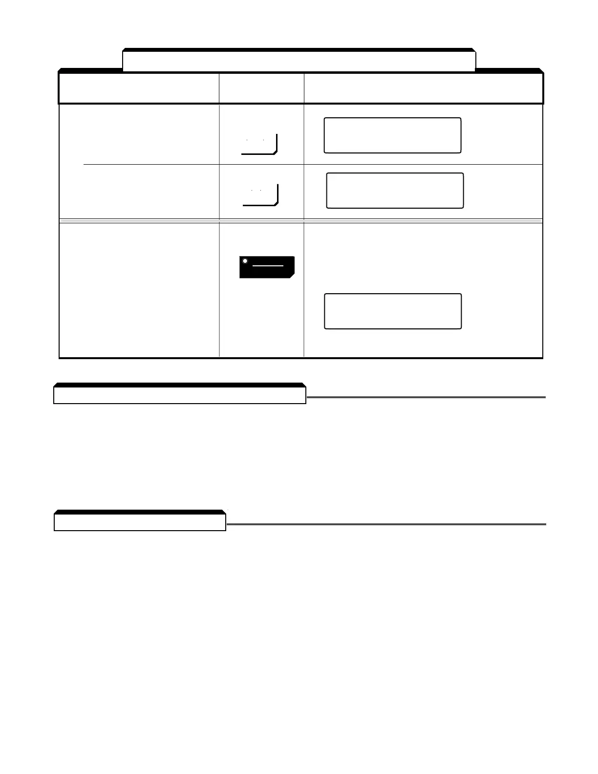
DIGITAL OPERATOR
DESCRIPTION KEY SEQUENCE DISPLAY
➄ (Continued)
• Write-in set value Press
• Select output frequency Press
monitor display.
➅ Stop
• Decelerates to a stop. Press RUN LED blinks while
motor is being decelerated
and STOP/RESET LED
turns "
ON"; then RUN LED
turns "
OFF"
Table 2-1. Test Run With Digital Operator - Continued

 Loading...


