n043 : Analog Input Selection
(AnalogInput Sel)
To input an auto frequency reference from external terminals, program n043 to
“FV=MSTR FI=AUX” (“0”) for a voltage reference (0 to 10V) or to " FV=AUX FI=MSTR "
(“1”) for a current reference (4 to 20mA).
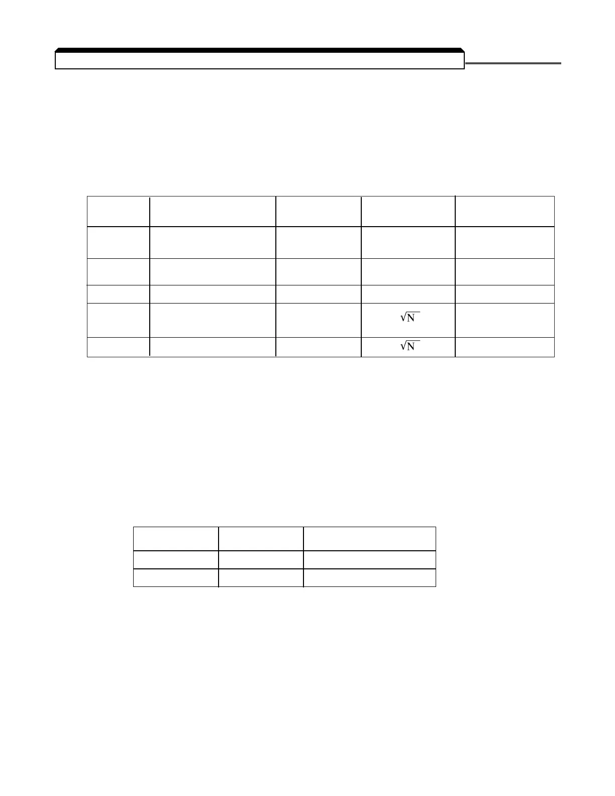
LED LCD Terminal FV Terminal FI FV/FI Switching
Setting Setting Function Function Allowed
(1)
0* FV=MSTR FI=AUX* Auto Speed Manual Speed Yes
Reference Reference
1 FV=AUX FI=MSTR Manual Speed Auto Speed Yes
Reference Reference
2 FV=RST FI=MSTR
(3)
Fault Reset
(2)
Auto Speed No
3 FV=MSTR FI=SQRT Auto Speed No
Reference
4 FV=RST FI=SQRT Fault Reset** No
n044 : Terminal FI Signal Level Selection
(Terminal FI Sel)
To change the control circuit terminal FI input level, program n044 .
LED LCD
Setting Setting Terminal FI Signal Level
0 0-10VDC 0 to 10 V input
1* 4-20mA* 4 to 20 mA input
NOTE: In addition to setting parameter n044 to “0-10VDC” (" 0 ") for a voltage
input, jumper J1 on the drive Control PCB must be cut.
Examples of wiring the drive for frequency references from various sources are shown on the
next page.
(1) A Multi-function input can be programmed to switch the analog terminal function.
This is accomplished by programming a multi-function input parameter (n036 thru n040) to = “Master
Fref Sel”(“9”). Note that if n043 is then set to “FV=RST FI=MSTR” (“2”), an OPE6 fault will occur.
(2) A fault reset will occur when the voltage on this terminal exceeds 6.0V.
(3) When n043 is set to “FV=RST FI=MSTR” (“2”) and PID selection n084 is NOT disabled (set to
anything other than “Disabled”(“0”)) an OPE6 fault will occur.
5-15
5.11 FREQUENCY REFERENCE INPUT SIGNALS (AUTO/MANUAL)

 Loading...


