- vi -
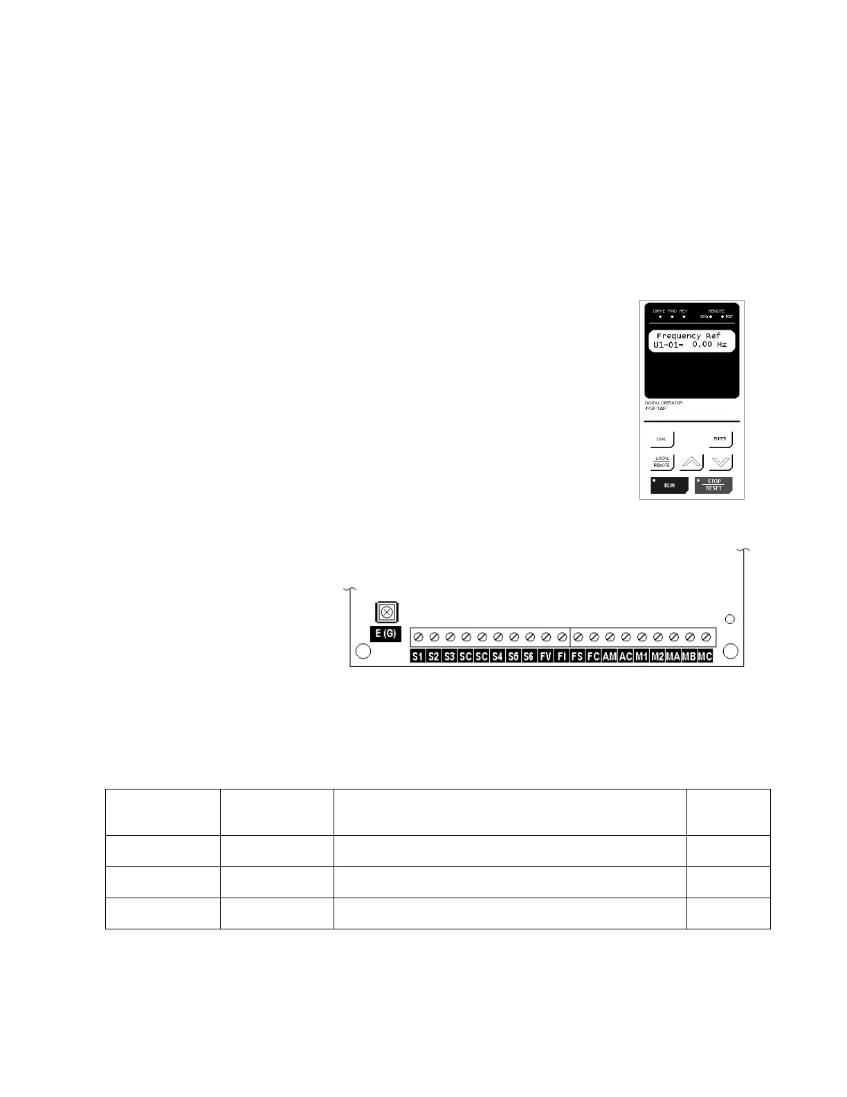
4. Replace cover and apply input power – digital operator shows “Frequency Ref
00.0 Hz”; DRIVE, SEQ, REF & STOP LEDs are on. Press the LOCAL / REMOTE
button. The SEQ & REF LEDs should go off. Press and hold the UP ARROW button
until the display shows “6.0 Hz, then press the ENTER button. Press the RUN button
and note the direction of motor rotation. If rotation is incorrect, remove power, wait for
charge light to go out, then switch wires between terminals T1 and T2. Replace the front
cover and apply input power.
5. Digital Operator
To access a “Quick Start” display, press the DSPL button until the desired display is on
the screen. Use the UP and DOWN keys to adjust the value then press the ENTER key.
To access a parameter, press the DSPL button until the word
“Parameter” is on the upper left side of the screen. Use the UP and
DOWN keys until the desired parameter number is on the right side
of the screen, then press ENTER. Use the UP and DOWN keys to
adjust the value then press ENTER then DSPL.
Before the drive will accept a RUN command, the DRIVE LED must
be on. Press the DISPL key until the DRIVE LED comes on. For
more specific information on the digital operator, Section 4.
6. Control Terminal Wiring – Remove power and wait for the charge
light to go out before making control terminal connections. Control wiring should be
sized 16 to 20 AWG.
Control wiring should be
shielded, with the shield
wire connected to terminal
E(G) and the other end of
the shield left open. As
shown at right there are
two SC terminals provided
for wiring convenience.
7. Choose a configuration from Table 1 below. Each example listed below contains a
control wiring diagram, operation explanation, and all necessary programming.
Table 1: Drive Configuration Examples
Sequence*
Source
(Run / Stop)
Reference*
Source
(Motor Speed)
Description
Example
Page
Digital Operator Digital Operator This method requires no control wiring connections to the
drive. It is most often used during startup of the drive.
Example 1
2-wire
4-20 mA
This method is the same as Example 2 but the reference
comes from a remote 4 – 20 mA source such as a PLC.
Example 2
3-wire
Speed
Potentiometer
This method is similar to Example 3, but utilizes a remote
mounted speed control (potentiometer).
Example 3
* For a more detailed explanation of sequence and reference, see Definitions page.
GPD506/P5 Control Terminals

 Loading...


