14.6 LIO-06 Module
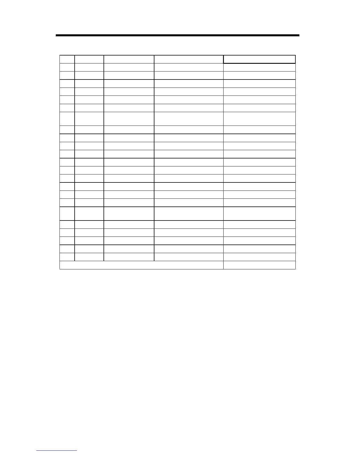
14.6.19 Standard Cable Wiring Table
103
28 White — N.C.
29 Yellow — PB+ B_Pulse+
30 Pink — PB- B_Pulse-
31 Orange — — GND Pulse input ground
32 Gray — — N.C.
33 White — — N.C.
34 Yellow — — PILC12V
C-Phase latch input common
(12V)
35 Pink — — PIL C-Phase latch input
36 Orange — — — N.C.
37 Gray — — — N.C.
38 White — — — DICOM Digital Input Common
39 Yellow — — — DI_01 Digital Input 1
40 Pink — — — DI_03 Digital Input 3
41 Orange — — — Continuous DI_05 Digital Input 5
42 Gray — — — Continuous DI_07 Digital Input 7
43 White — — — Continuous N.C.
44 Yellow — — — Continuous N.C.
45 Pink — — — Continuous DO_24V
Digital output 24V Power
Supply
46 Orange ———————— DO_01 Digital Output 1
47 Gray ———————— DO_03 Digital Output 3
48 White ———————— DO_05 Digital Output 5
49 Yellow ———————— DO_07 Digital Output 7
50 Pink ———————— DO_GND Digital output common ground
Shell Shield Wire
Pin Wire Color Markings Signal Name Function