14.2 AO–01 (Analog Output) Module
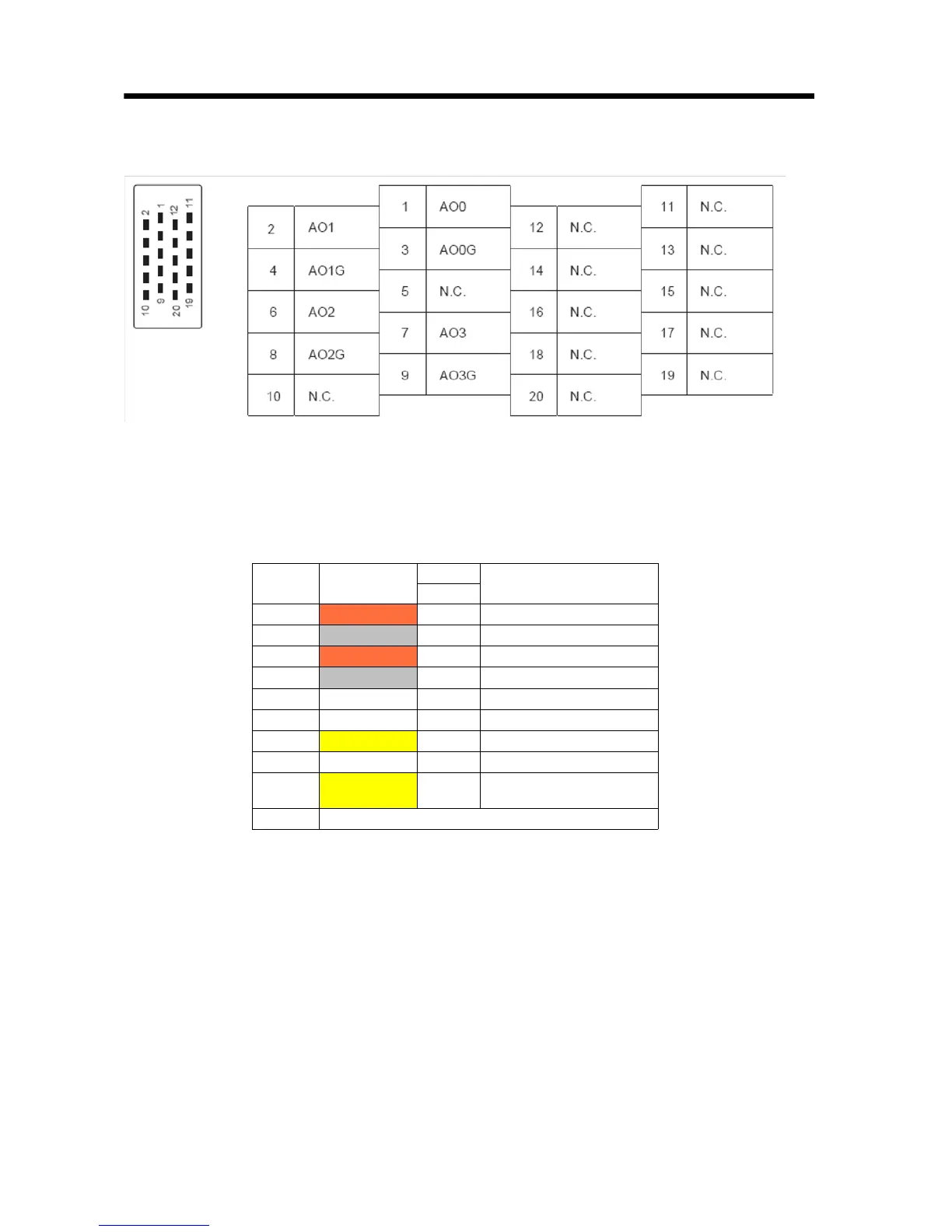
14.2.6 CN1 Pin Layout Diagram
60
14.2.6 CN1 Pin Layout Diagram
14.2.7 Standard Cable Wiring Table
The following shows the pin arrangement for standard cable
JEPMC-W6090.
Pin Wire Color
Marking
Function
Color
1
Orange Red Analog Output 0
2
Gray Red Analog Output 1
3
Orange Black Ground 0
4
Gray Black A_Pulse+
5
6
White Red Pulse input ground
7
Yellow Red –
8
White Black –
9
Yellow Black
C-Phase latch input
common (5V)
10~20
Twisted-pair cable