User Constant Tables
5-81
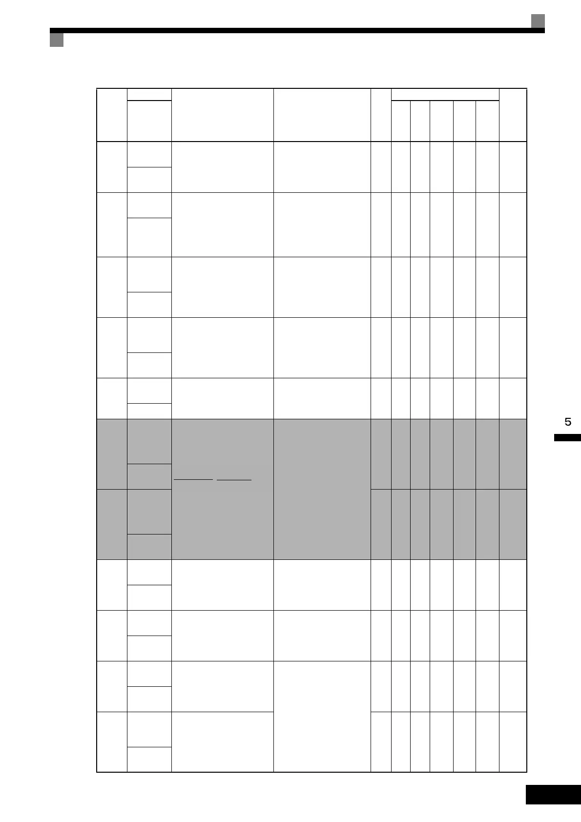
U1-24
PID feed-
back value
Monitors the feedback value
when PID control is used.
The input for the max. fre-
quency corresponds to 100%.
10 V: Max. frequency
(-10 to 10 V possible)
0.01
%
AAAAA57H
PID Feed-
back
U1-25
DI-16H2
input status
Monitors the reference value
from a DI-16H2 Digital Refer-
ence Board.
The value will be displayed in
binary or BCD depending on
user constant F3-01.
(Cannot be output.) - A A A A A 58H
DI-16 Ref-
erence
U1-26
Output volt-
age refer-
ence (Vq)
Monitors the Inverter internal
voltage reference for motor
secondary current control.
10 V: 200 VAC (400 VAC)
(-10 to 10 V possible)
0.1
V
NoNoAAA59H
Voltage Ref
(Vq)
U1-27
Output volt-
age refer-
ence (Vd)
Monitors the Inverter internal
voltage reference for motor
excitation current control.
10 V: 200 VAC (400 VAC)
(-10 to 10 V possible)
0.1
V
NoNoAAA5AH
Voltage Ref
(Vd)
U1-28
Software
No. (CPU)
(Manufacturer’s CPU software
No.)
(Cannot be output.) - A A A A A 5BH
CPU ID
U1-29
Output
power
lower 4 dig-
its
Monitors the Inverter’s output
power. The display is split into
upper digits and lower digits in
the following way.
Example: If the output power
is 12345678.9 kWh, the dis-
play will be as follows:
U1-29: 678.9 kWH
U1-30: 12345 MWH
Range: 0.0 to 32767999.9
(Cannot be output.)
0.1
kWH
A A A A A 5CH
kWh Lower
4 dig
U1-30
Output
power
upper 5 dig-
its
MWH
A A A A A 5DH
kWh Upper
5 dig
U1-32
ACR out-
put of q axis
Monitors the current control
output value for the motor sec-
ondary current.
10 V: 100%
(-10 to 10 V possible)
0.1
%
NoNoAAA5FH
ACR(q)
Output
U1-33
ACR out-
put of d axis
Monitors the current control
output value for the motor
excitation current.
10 V: 100%
(-10 to 10 V possible)
0.1
%
NoNoAAA60H
ACR(d)
Output
U1-34
OPE fault
constant
Shows the first constant num-
ber where an OPE fault was
detected.
(Cannot be output.)
-AAAAA61H
OPE
Detected
U1-35
Zero-servo
movement
pulses
Shows the number of PG
pulses times 4 for the move-
ment range when stopped at
zero.
1 No No No A No 62H
Zero Servo
Pulse
Con-
stant
Number
Name
Description
Output Signal Level
During Multi-Function
Analog Output
Min.
Unit
Control Methods
MEMO-
BUS
Regis-
ter
Display
V/f
V/f
with
PG
Open
Loop
Vec-
tor
1
Flux
Vec-
tor
Open
Loop
Vec-
tor
2
U1-30 U1-29
.
kWH

 Loading...


