6-13
IM AQ1210-01EN
Analyzing Waveforms
6
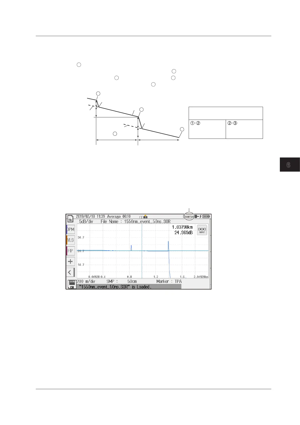
6 Point Markers
The instrument measures using the 6-point method when there are two adjacent splice loss events.
The instrument uses the following six points to perform the measurement: the first splice loss start
point
, start point Y1 used to calculate the approximation line, end point Y3 used to calculate the
approximation line, the second splice loss start point
, the second splice loss end point Y2, and the
measurement end point
. At the position of marker
, the level difference between the approximation
line Y1–Y3 and the approximation line Y2–
is calculated as the splice loss.
Y2
Y1
Y3
a (dB)
b (dB)
c (km)
e (dB)
f (km)
Approximation
line Y1–
Approximation
line Y1–Y3
1
2
3
3
Splice loss
Return loss
b
c
b/c
dB
km
dB/km
a
e
f
e/f
dB
dB
km
dB/km
Marker information
Setting the Amount That the Cursor Moves
Press the rotary knob to set whether to move the cursor in coarse steps or fine steps. Tap the screen
to set the cursor to move in fine steps.
COARSE: The cursor moves a large amount.
FINE: The cursor moves a small amount.
The amount that the cursor is set to move is displayed in the upper right of the screen.
Amount of cursor movement
6.1 Operating Cursors and Markers

 Loading...


