6-12
IM AQ1210-01EN
Explanation
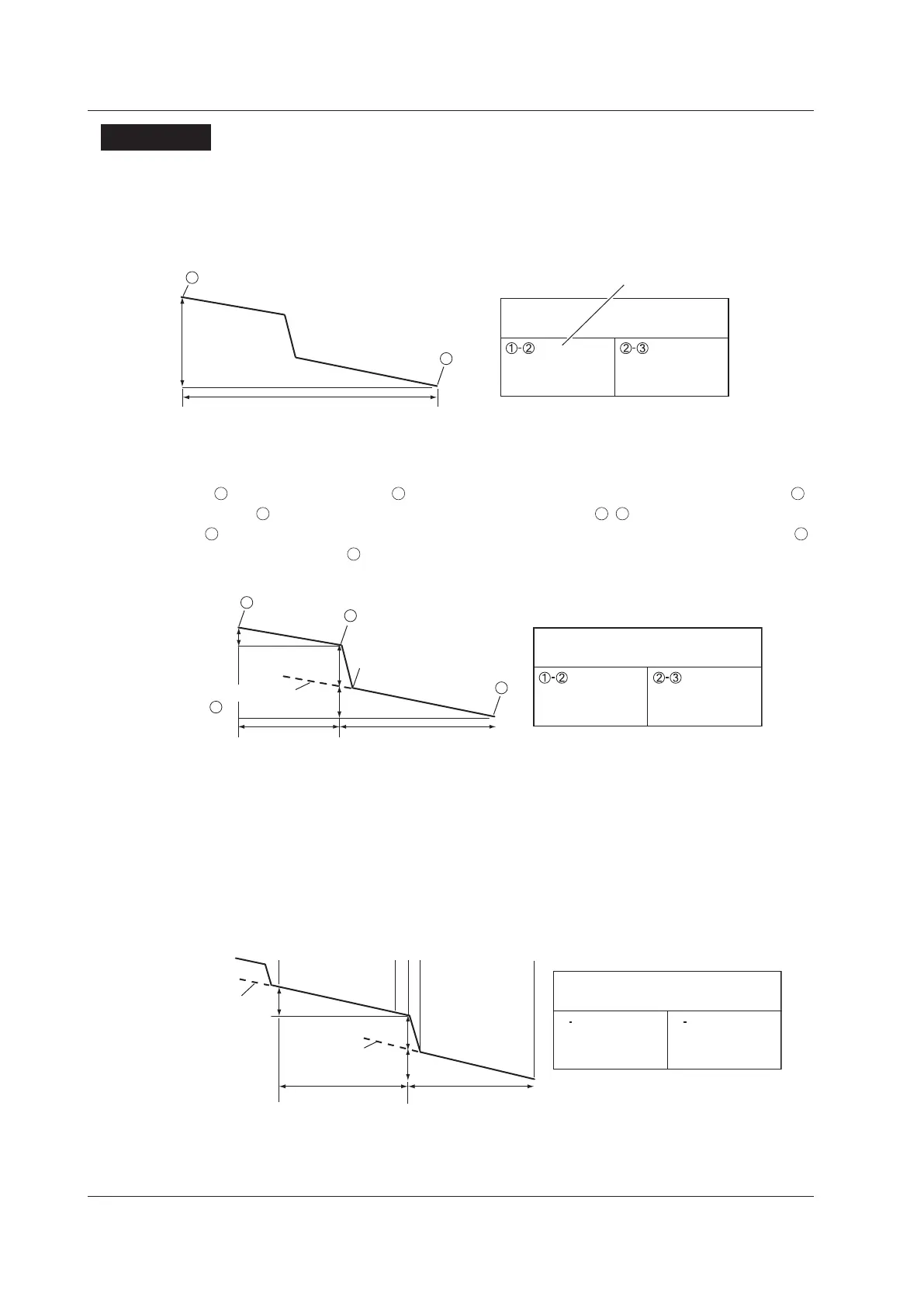
2 Point Markers
The instrument measures the distance and the loss between two points. If reflection is detected
between the two points, the return loss is also measured. The splice loss value changes depending
on the approximation method that you have specified. This can be used when Marker Mode is set to
Marker or Line.
Splice loss a (dB)
(Total loss)
d (km)
(n when Marker Mode is set to Line)
(E when Marker Mode
is set to Line)
2
Splice loss
Return loss
20
20
1
dB
km
dB/km
Splice loss
4 Point Markers
The instrument uses the following four points to perform the measurement: the measurement start
point
, the splice loss start point
, the splice loss end point Y2, and the measurement end point
. At position
, the level difference between the approximation line
–
and the approximation line
Y2–
is calculated as the splice loss. The splice loss changes greatly depending on the position of
.
Set the correct position for
. The splice loss value changes depending on the approximation method
that you have specified. This can only be used when Marker Mode is set to Marker.
Y2
b (dB)
e (dB)
c (km) f (km)
3
2
Splice loss
Return loss
b
c
b/c
dB
km
dB/km
a
e
f
e/f
dB
dB
km
dB/km
Marker information
a (dB)
3
5 Point Markers (when the marker mode is Line)
The instrument uses the following five points to perform the measurement: the near-end point (n), a
point (N) that is used to calculate the near-end side's approximation line, a point (E) where splice loss
is detected, a point (F) that is used to calculate the far-end side's approximation line, and the far-end
point (f). At position E, the level difference between the approximation line n–N and the approximation
line F–f is calculated as the splice loss. The splice loss changes greatly depending on the position of E.
Set the correct position for E. The splice loss value changes depending on the approximation method
that you have specified. This can only be used when Marker Mode is set to Line.
a (dB)
b (dB)
c (km)
e (dB)
f (km)
Approximation
line F–f
n E E f
Splice loss
Return loss
b
c
b/c
dB
km
dB/km
a
e
f
e/f
dB
dB
km
dB/km
Marker information
6.1 Operating Cursors and Markers
 Loading...


