3-13
IM AQ1210-01EN
Performing Real-time Measurement
3
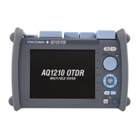
Comparing waveform data before the construction and after the construction
8.
Tap the Work Trace Comparison soft key, the Trace Shift soft key, and then the Trace Shift
Right soft key. The waveform data (captured waveform) before the construction moves to
the right side of the screen. Use Trace Shift Right or Trace Shift Left depending on the
differences in the start points before the construction and after the construction. In this example,
because the distance between the start point and the end point after the construction is long,
the waveform data before the construction is moved to the right side.
construction
Waveform data before construction
(captured waveform)
Moved to
the right
By overlapping the waveform data before construction and
that after construction, you can check that there are no
changes in the events.
A
B
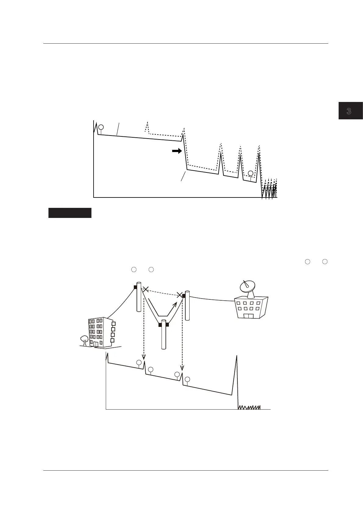
Explanation
When installed fibers are moved because of road construction or other external factors (rerouting
work), using this feature enables you to compare the event waveform before the construction to that
after the construction. This makes it easy to check the presence of obstacles caused as a result of the
rerouting work.
The markers of 4 Point Monitor are used to measure two sections as loss measurements for when the
optical fiber is switched. The measurement of the two sections is performed the marker pairs
and
and the marker pairs
and
.
A
B
C
D
3.4 Rerouting Work
 Loading...


