86
IM FG410-01EN
4. BASIC OPERATION
4.7.11 SettingPWM
The duty of square waves and pulse waves varies according to the instantaneous value of the
modulation signal.
For the manipulation methods that are common with the modulation setting screen, refer to p.74
and p.76 .
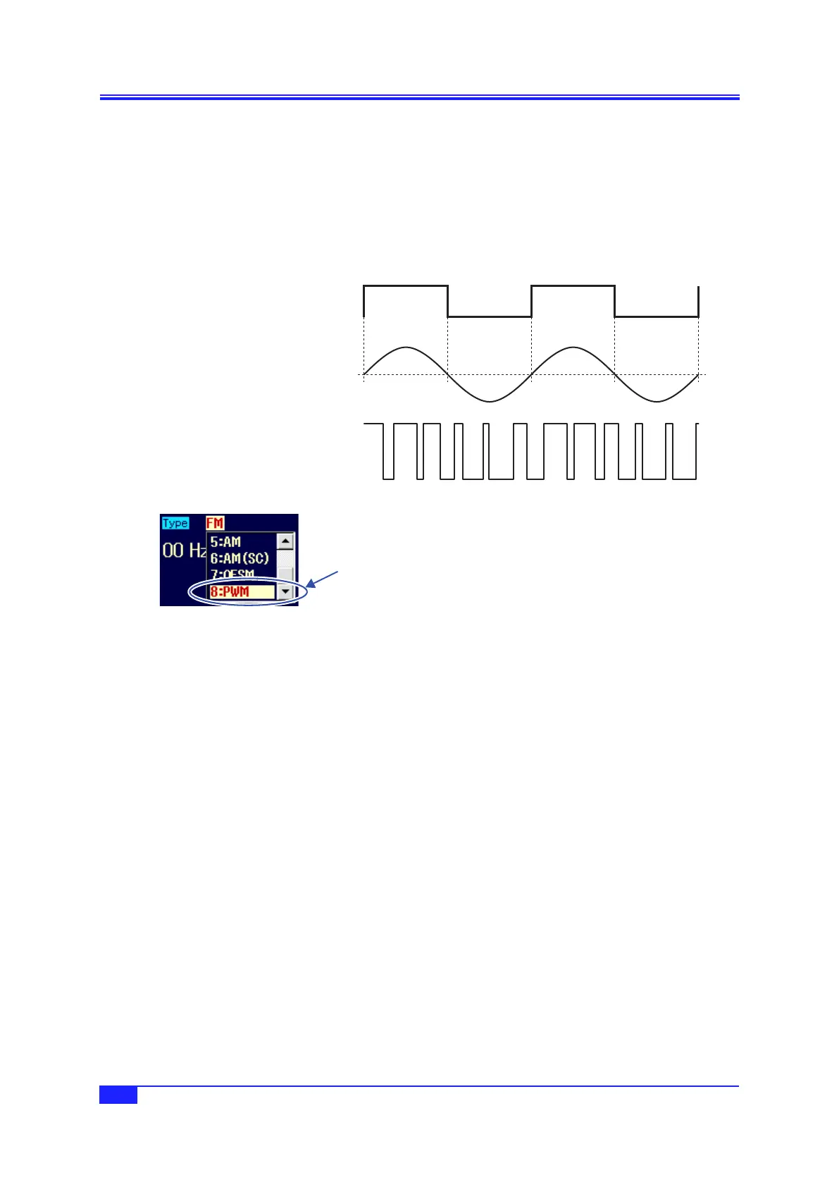
a) PWMexample
The duty of the output signal grows larger when the modulation signal swings to the positive side.
Modulation sync signal
(during internal modulation)
Output signal
Modulation signal
b) SelectingPWM
When [Mode] (modulation mode) is
set to [Modulation] (modulation), set
[Type] (modulation type) on the 2nd
page of the setting screen to [PWM]
(PWM).
c) Waveforms for which PWM is not possible
PWM is possible only for square waves and pulse waves.
PWM is not possible for other waveforms.
d) SettingitemsrequiredforPWM
Set [Duty] (carrier duty) on the 1st page of the setting screen.
Set [Deviation] (peak duty deviation) on the 2nd page of the setting screen.
The output duty varies in the range of carrier duty ± peak duty deviation.
When the pulse wave is used, the pulse width of the carrier is fixed to the duty setting and cannot be
set with time.
If [Source] (modulation source) is set to [Int] (internal), set [ModFctn] (modulation waveform) and
[ModFreq] (modulation frequency).
If [Source] (modulation source) is set to [Ext] (external), input the modulation signal to the external
modulation/addition input terminal. In the case of ±1 V input, the prescribed peak duty deviation
results.
Select [PWM] in
[Type] and then
press the ENTER
key.
 Loading...