79
IM FG410-01EN
4.7.4 SettingFM
TThe output frequency varies according to the instantaneous value of the modulation signal.
For the manipulation methods that are common with the modulation setting screen, refer to p.74
and p.76 .
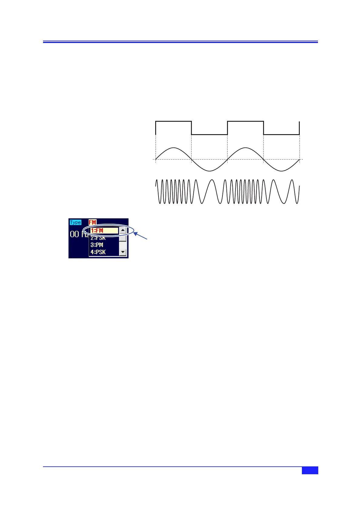
a) FMexample
Frequency shifting of the output signal grows larger when the modulation signal swings to the
positive side.
Modulation sync signal
(during internal modulation)
Modulation signal
Output signal
b) SelectingFM
When [Mode] (oscillation mode) is set
to [Modulation], set [Type] (modulation
type) on the 2nd page of the setting
screen to [FM] (FM).
c) Waveforms for which FM is not possible
FM is not possible for noise, pulse wave, and DC.
d) SettingitemsrequiredforFM
Set [Freq] (carrier frequency) on the 1st page of the setting screen.
Set [Deviation] (peak frequency deviation) on the 2nd page of the setting screen.
The output frequency varies according to the range of carrier frequency ± peak frequency deviation.
If [Source] (modulation source) is set to [Int] (internal), set [ModFctn] (modulation waveform) and
[ModFreq] (modulation frequency).
If [Source] (modulation source) is set to [Ext] (external), input the modulation signal to the external
modulation/addition input terminal. In the case of ±1 V input, the prescribed peak frequency
deviation results.
Select [FM] in
[Type] and then
press the ENTER
key.
4.7 Modulation Setting and Manipulation
 Loading...