16
IM FG410-01JA
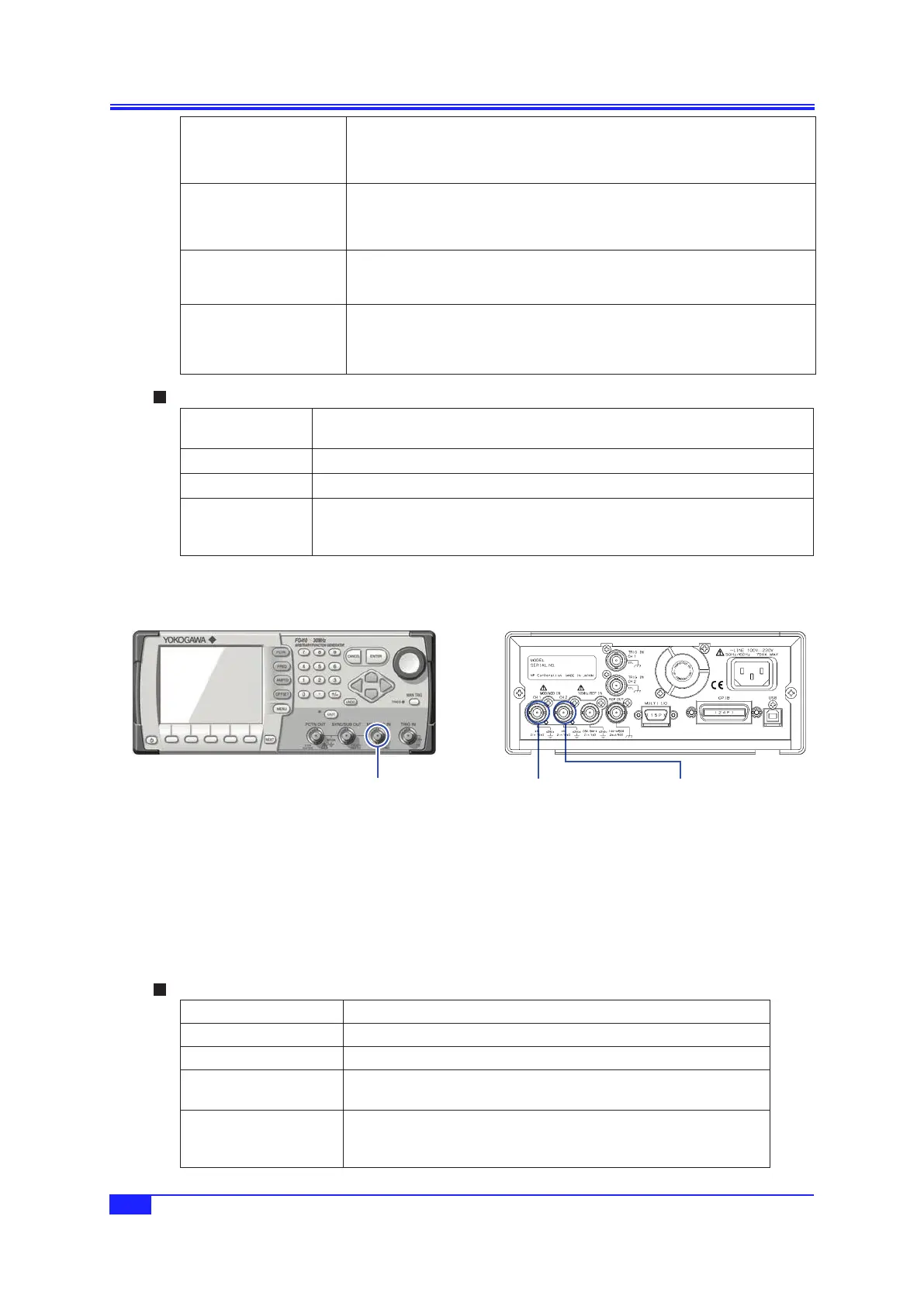
3. PANELS AND I/O TERMINALS
Modulation mode with
internal modulation source
p. 78
•
Reference phase sync signal
•
Internal modulation signal (
-
3 V to +3 V/open)
•
TTL level logic signal synchronized with internal modulation signal
Sweep oscillation mode
p. 96
•
Reference phase sync signal
•
Sweep X drive signal (0 V to +3 V/open)
•
TTL level logic signal synchronized with sweep, marker signal mixing possible
Burst oscillation mode
p. 112, p. 115, p. 119,
p. 124
•
Reference phase sync signal
•
TTL level logic signal synchronized with burst oscillation
Sequence oscillation mode
“6.2 Basics” in the
Application Instruction
Manual
•
Reference phase sync signal
•
TTL level logic signal synchronized with sequence step
Output characteristics
Output voltage TTL level (low: 0.4 or lower; high: 2.7 V or higher),
-
3 V to +3 V/open, 0 V to +3 V/
open
Output impedance
50
Ω
Load impedance
50
Ω
or higher recommended
Signal GND Same potential as same channel waveform output, insulated from housing (42 Vpk
max.).
FG420: Insulation also between channels (42 Vpk max.)
3.2.3 Externalmodulation/additioninput(MOD/ADD IN)
FG420FG410
MOD/ADD IN
[Insulated from housing]
CH1
MOD/ADD IN
[Insulated from housing]
CH2
MOD/ADD IN
[Insulated from housing]
When the modulation source is external, except for FSK and PSK, an external modulation signal is
input. In the case of the FSK and PSK, the external trigger input is used as external modulation signal
input.
When not used as external modulation signal input, MOD/ADD IN may be used as the external
addition signal input. The gain during external addition is either ×2 or ×10.
External modulation input:
p. 77.
External addition input:
p. 61.
InputSpecifications
Input voltage ±1 V full scale
Maximum allowed input ±2 V
Input impedance
10 k
Ω
Input frequency During modulation: DC to 25 kHz
During addition: DC to 10 MHz (
-
3 dB)
Signal GND Same potential as same channel waveform output, insulated from housing
(42 Vpk max.).
FG420: Insulation also between channels (42 Vpk max.)
 Loading...