137
IM FG410-01EN
Leading edge time, trailing edge time
Setting range 15.0 ns to 58.8 Ms (3 digits or 0.1 ns resolution)
Leading edge time and trailing edge time independently settable
Minimum setting value Largest of either 0.01% of period or 15 ns
Pulse width, leading edge time, trailing edge time limits
The pulse width time, leading edge time, trailing edge time, and period are mutually constrained
by the following equations.
The duty is converted from pulse width time / period.
(leading edge time + trailing edge time)
x
0.85 ≤ pulse width time
pulse width time £ period
-
(leading edge time + trailing edge time)
x
0.85
Overshoot 5% or less typ.
Jitter 500 ps rms or less typ. (10 kHz or higher)
2.5 ns rms or less typ. (under 10 kHz)
7.5.4 Rampwave
Symmetry setting range 0.00% to 100.00% (0.01% resolution)
7.5.5 Parameter-variablewaveforms
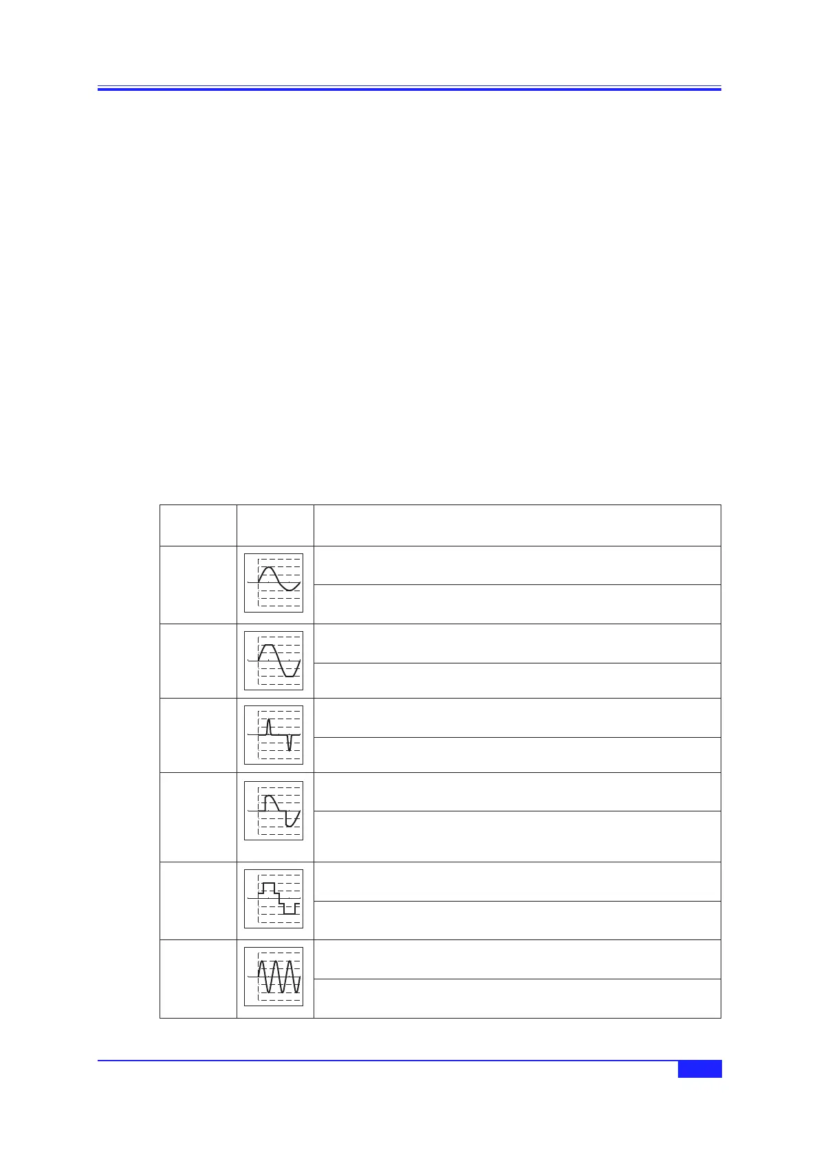
a) Steadysinegroup
Waveform
Name
Waveform
Example
DescriptionandVariableParameters
Unbalanced
sine
1.5
1.0
0.5
0
-
0.5
-
1.0
-
1.5
Waveform for which the amplitudes of the first half cycle and second half cycle
of a sine wave can be changed independently
First-half amplitude (
-
100.00% to 100.00%)
Second-half amplitude (
-
100.00% to 100.00%)
Clipped sine
1.5
1.0
0.5
0
-
0.5
-
1.0
-
1.5
Waveform obtained by clipping the top and bottom of the amplitude of a sine
wave
Clip rate (0.00% to 99.99%)
CF controlled
sine
1.5
1.0
0.5
0
-
0.5
-
1.0
-
1.5
Waveform obtained by extracting only the 90° and 270° neighborhood of a sine
wave and expanding the amplitude
Crest factor (1.41 to 10.00)
Conduction
angle
controlled
sine
1.5
1.0
0.5
0
-
0.5
-
1.0
-
1.5
Waveform obtained by extracting only the front or back of each half cycle of a
sine wave
Conduction angle (
-
180.00° to 180.00°)
Remark: In the case of a positive/negative conduction angle, back/front
conduction angle
Staircase sine
1.5
1.0
0.5
0
-
0.5
-
1.0
-
1.5
Staircase shaped sine wave
Number of steps (2 to 100)
Multi-cycle
sine
1.5
1.0
0.5
0
-
0.5
-
1.0
-
1.5
Waveform obtained by continuing sine for several cycles
Number of cycles (0.01 to 50.00)
Start phase (
-
360.00° to 360.00°)
7.5 Signal Characteristics
 Loading...